VI.BE.MAC.S.p.A.
pag.21
17. CONTROL CIRCUIT
The equipment uses an electro-pneumatic sequential circuit, managed entirely by the machine's software
(FULL LOGIC AUTOMATION) free of electronic disturbance and
in compliance with the directive
89/336/CEE regarding electro-magnetic compatibility.
The following are used in the circuit:
17.1 ELECTRIC LIMIT STOPS for LOADER
Two limit stops are used, to send a signal to the control circuit that the Loader cylinder in the equipment has
performed its movement.
TYPE FUNCTION
MS10 Loader Carriage Cylinder Closed
Signals lowering of 1° material blocking clamp
MS32 Loader Carriage Cylinder Open
Lowers the 2° material blocking clamp and at the start of the
sewing cycle in Automatic Operation
17.2. FLOW REGULATORS
Two models are used to regulate the speed of movement of the cylinders in the equipment.
They are used as a BRAKE for the outlet of air from the cylinder.
TYPE FUNCTION
"C" Screw-type flow regulator in the Unloader
AS1201FM5O4 Knob-type micro-regulator in the equipment and on solenoid valve EV9
SCO 604 1/8 Screw-type flow regulator for Loader cylinder speed located in the expansion
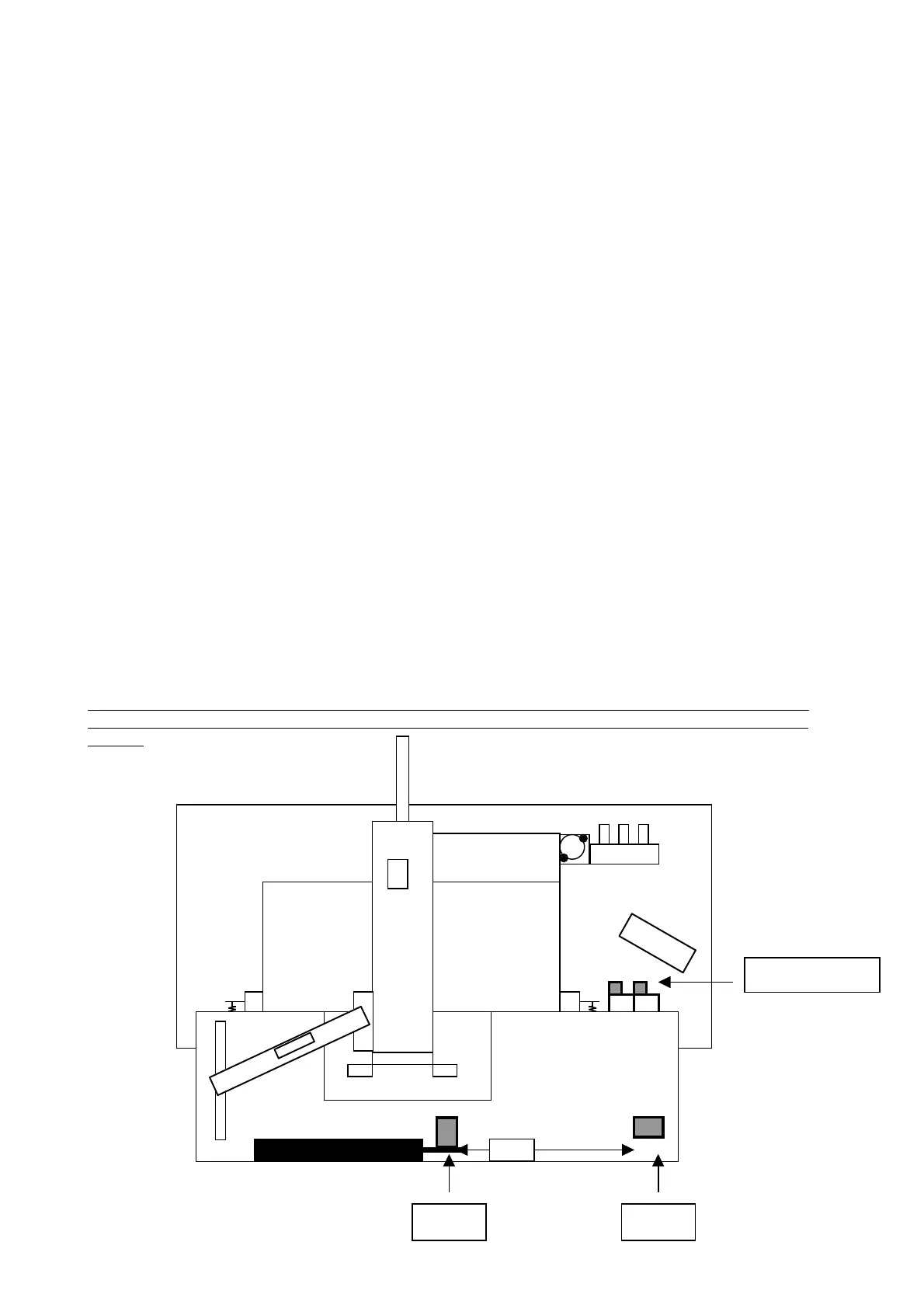
17.3. LOADING CYLINDER EXPANSIONS
On the right-hand side of the machine, under the Loader plate are two cylinder expansions with two type
SCO 604 1/8 flow regulators on the end.
The right regulator controls the return speed of the loading carriage
The left regulator controls the advance speed of the loading carriage.
ADJUSTMENT
Open the two regulators to maximum and close them by three turns.
ATTENTION: On the two ends of the loading cylinder there are regulators for the braking in the final 5 mm
of the stroke of the cylinder in both directions. Close the regulators completely and open them by 1/2 to 3/4
of a turn.
SCO 604 1/8
MS10 MS32