OPERATION CUTMASTER 10MM, 12MM
Manual 0-5230 4-1 Operation
SECTION 4 SYSTEM:
OPERATION
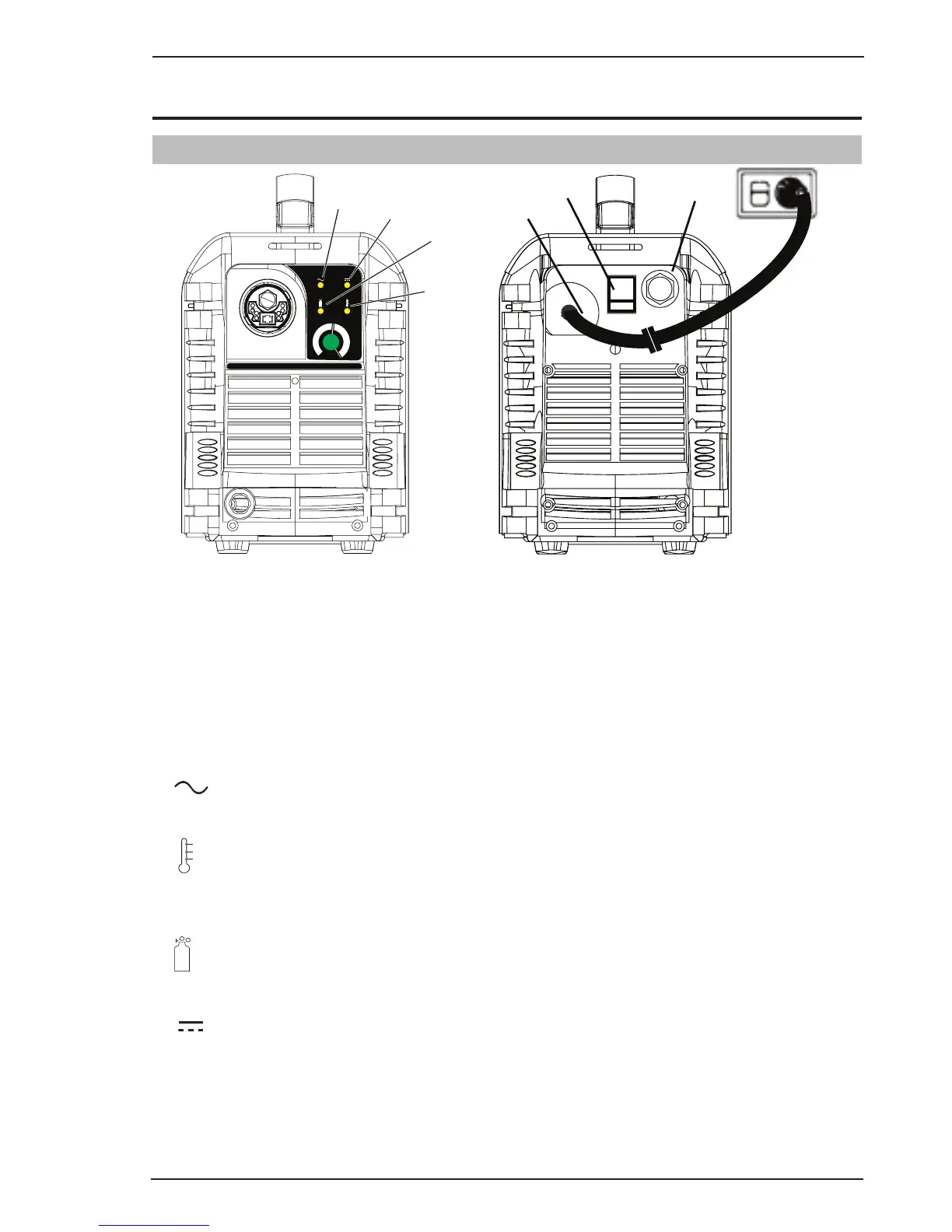
4.01 Control Panel
A
30
20
40
Art # A-10218
CUTMASTER
®
AC Indicator
Overheat
Indicator
Air Indicator
DC Indicator (Ready)
Air Inlet,
1/4” NPT
On/O
Switch
Power Cord
12mm
1. ON/OFF Switch (Power Switch)
Controls input power to the Power Source. I is ON, O is OFF.
2. (A) Output Current Control
Sets the desired output current. If the overload protection (fuse or circuit breaker) on the input power
circuit opens frequently, either reduce cutting output, reduce the cutting time, or connect the unit to more
adequate input power. For 240V input power, the maximum output is 40 Amps. Refer to Section 2 for input
power requirements.
3.
AC Indicator
Steady light indicates Power Source is ready for operation.
4.
OVERHEAT Indicator (TEMP Indicator)
Indicator is normally OFF. Indicator is ON when internal temperature
exceeds
normal limits. Allow the unit
to run with the fan ON until the temp indicator turns OFF.
5.
AIR Indicator
AIR indicator light should be ON when there is sufficient gas pressure.
6.
READY (DC Indicator)
Indicator is ON when DC output circuit is active.
Figure 4-1 - Front Control Panel Figure 4-2 - Rear Controls