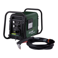
ASSEMBLY PROCEDURE CUTMASTER 10MM, 12MM
Manual 0-5230 8-5 Assembly Procedures
8.04 Installing Main Control PCB and Clear Cover Sheet
1. Install 4 screws.
2. Plug harness into HF/QF connector
3. Plug harness into MB connector
4. Plug harness into SOURCE&TIP connector
5. Plug harness into DRIVE connector
6. Plug harness into U-D connector
7. Plug harness into WA connector
8. Plug harness into FAN connector
9. Plug harness into TRANF-IFB connector
10. Plug harness into WV connector
11. Plug harness into D-PORT connector
12. Plug harness into OT connector
13. Plug harness into PRESSURE connector
14. Plug harness into GUN&TEST connector
15. Install clear protective sheet.