CUTMASTER 10MM, 12MM OPERATION
Operation 4-4 Manual 0-5230
4.03 Sequence of Operation
The following is a typical sequence of operation for this Power Source.
1. Place the ON/OFF switch on the Power Source to ON (up) position.
a. AC indicator turns ON; fan turns ON.
NOTE
During initial power up, there will be a delay of about 2 seconds before the AC Indicator light will illumi
-
nate and the pre-flow gas and fan starts. The gas will automatically flow from torch for approximately
10 seconds (only after the AC Indicator lamp is illuminated) (The AC Indicator lamp and fan turns ON
approximately 2 seconds after the ON/OFF switch is enabled), this is a process that makes sure all
inputs (gas, input power, torch connection, and torch parts) are acknowledged for proper operation.
2. Wear protective clothing, including welding gloves and appropriate eye protection (See Table 1-1). Place
tip on workpiece and pull trigger. Arc will initiate and start cutting material.
• Standoff Cutting With Hand Torch
NOTE
For best performance and parts life, al
-
ways use the correct parts for the type of
operation.
A. The torch can be comfortably held in one
hand or steadied with two hands. Position
the hand to press the Trigger on the torch
handle. With the hand torch, the hand may
be positioned close to the torch head for
maximum control or near the back end
for maximum heat protection. Choose
the holding technique that feels most
comfortable and allows good control and
movement.
NOTE
The tip should never come in contact with
the workpiece except during drag cutting
operations.
B. Depending on the cutting operation, do
one
of the following:
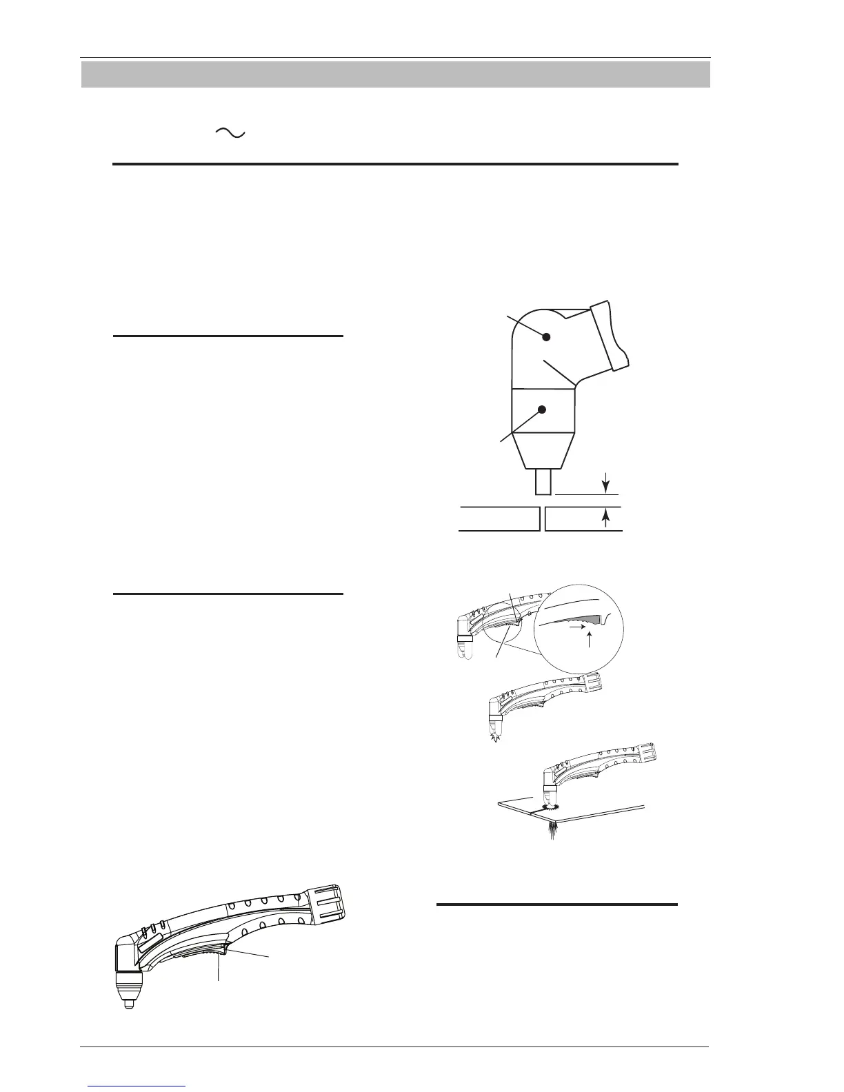
a). For drag cutting, place the tip on the
plate holding the torch at an angle to
the plate so that only one edge of the
tip is in contact with the plate. This
prevents damage to the tip during the
piercing process.
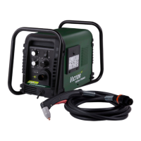
b). For standoff cutting, hold the torch
tip on the workpiece, pull the trigger.
After the arc is initiated lift the tip to
1/8" - 3/8" (3-4mm) off the work.
Art # A-09342
Trigger
Trigger Release
Figure 4-7 Torch Trigger Release
A-00024_AB
Shield Cup
Torch
Standoff Distance
1/8" - 3/8" (3 - 9mm)
Figure 4-8 Standoff Distance
3
4
2
1
Trigger Release
Art # A-11462
Figure 4-9 Standoff Cutting
NOTE
When the shield cup is properly installed,
there is a slight gap between the shield cup
and the torch handle. Gas vents through
this gap as part of normal operation. DO
NOT attempt to force the shield cup to close
this gap. Forcing the shield cup against
the torch head or torch handle can damage
components.