REPLACEMENT PARTS CUTMASTER 10MM, 12MM
Manual 0-5230 9-1 Replacement Parts
SECTION 9:
REPLACEMENT PARTS
C. Ordering Information
Order replacement parts by part number and
complete description of the part or assembly, as
listed in the parts list for each type item. Also
include the model and serial number of the torch.
Address all inquiries to your authorized distributor.
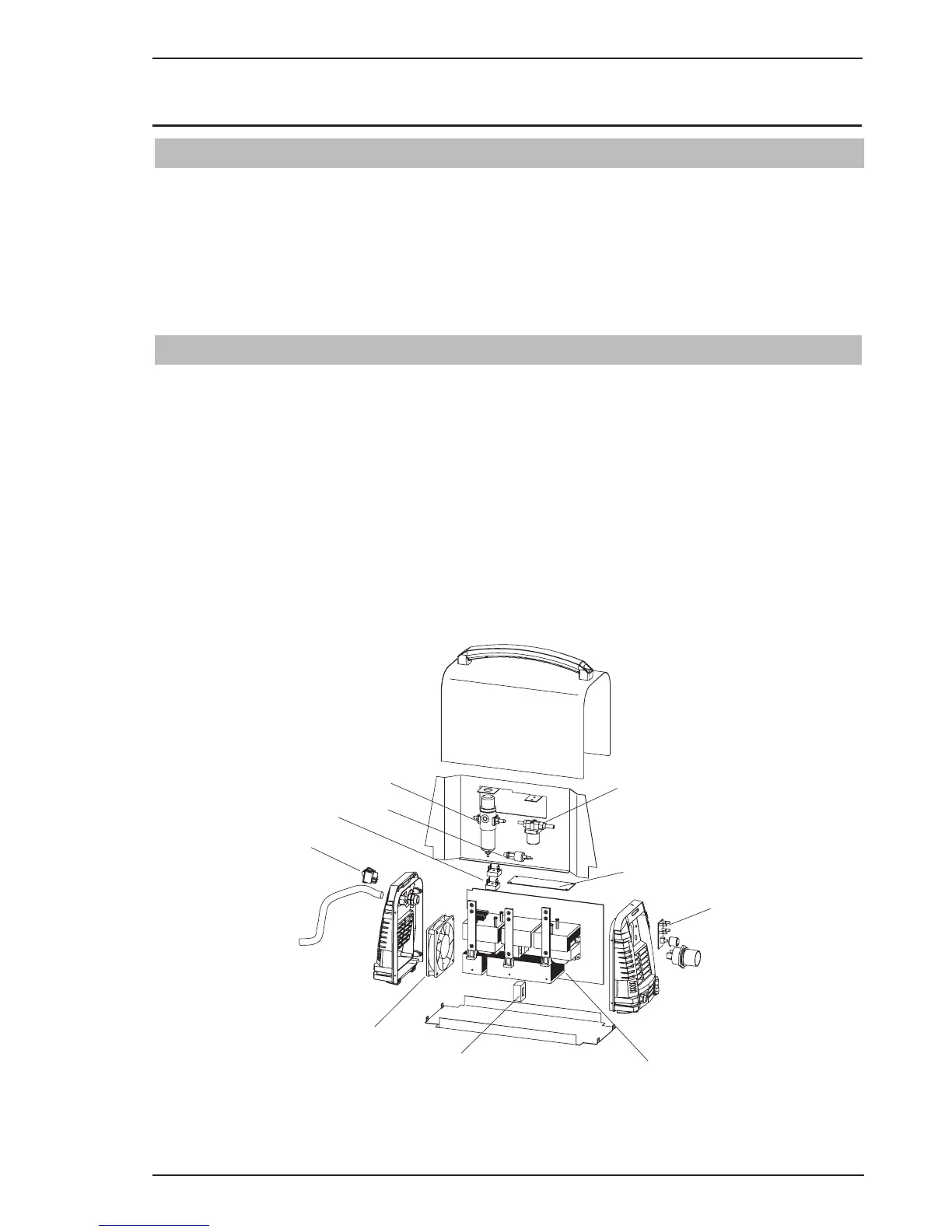
9.02 Power Source Replacement Parts
Item # Qty Description Catalog #
1 1 Logic PCB assembly 10mm & 12mm 9-0076
2 1 Control PCB assembly 10mm 9-7555
2 1 Control PCB assembly 12mm 9-0077
3 1 Main PCB assembly 10mm 9-7556
3 1 Main PCB assembly 12mm 9-0079
4 1 Air Regulator 10mm & 12mm 9-0081
5 1 Solenoid assembly 10mm & 12mm 9-0082
6 1 Pressure Switch 10mm & 12mm 9-0075
7 1 Hall Current Sensor 10mm & 12mm 9-0088
8 1 ON/OFF Switch 10mm & 12mm 9-0074
9 1 Cooling Fan 10mm & 12mm 9-0042
10 1 Input Rectifier 10mm & 12mm 9-0049
5
2
1
3
10
7
9
8
6
4
Art# A-10400
Parts 9-1 - Power Source
A. Parts List Breakdown
The parts list provides a breakdown of all replace-
able components.
B. Returns
If a product must be returned for service, contact
your distributor. Materials returned without proper
authorization will not be accepted.
9.01 Introduction