Troubleshooting 6-20 Manual 0-5230
CUTMASTER 10MM, 12MM TROUBLESHOOTING
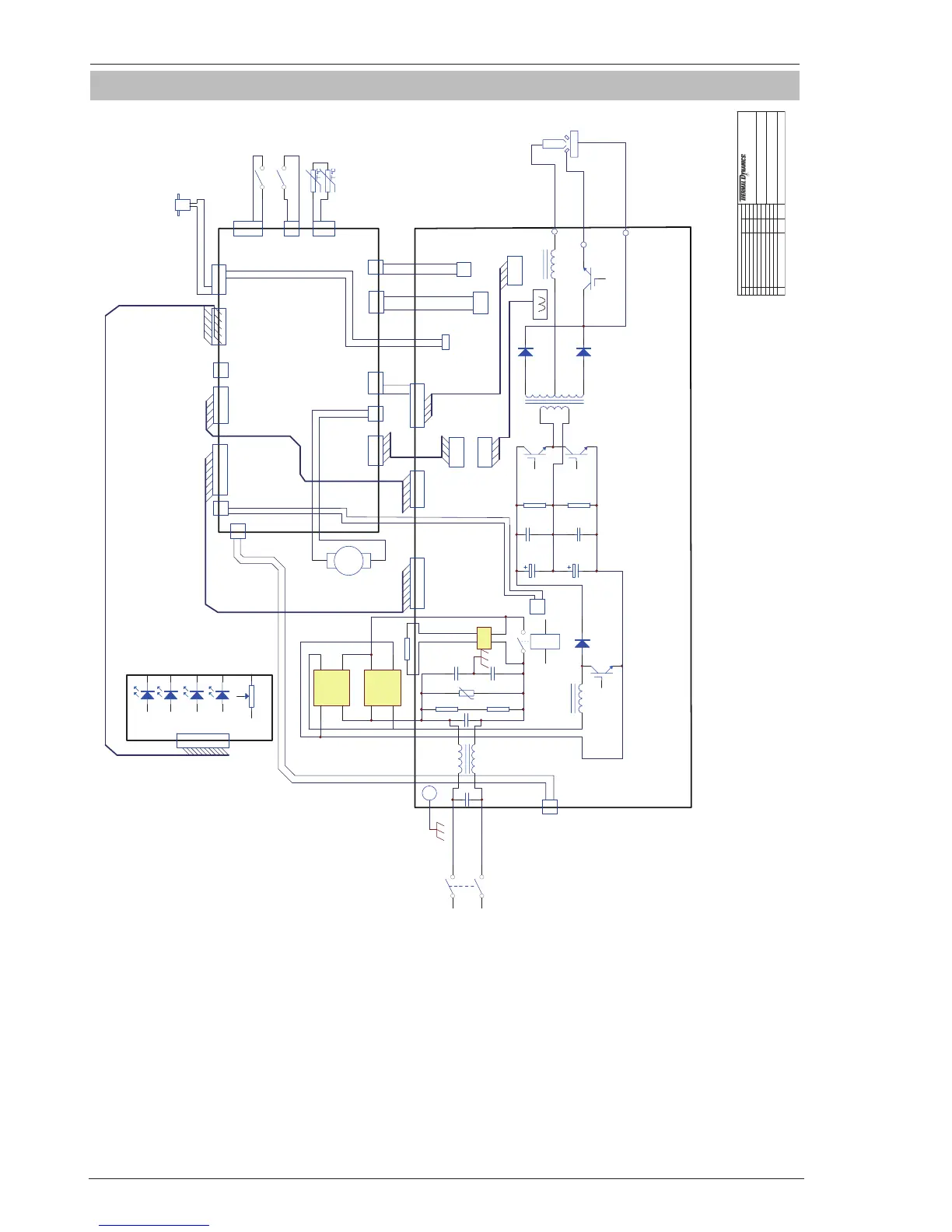
6.15 Circuit Diagram
Rev
Revision By Date
A THERMADYNE Company
NOTE:
TITLE:
CUTMASTER 42 230V SINGLE PHASE 50/60Hz
SCHEMATIC
Information proprietary to THERMAL DYNAMICS CORPORATION
Not for Release Reproduction or Distribution without writeen consent
Unless otherwise Specified resistors are in Ohms 1/4W 5%
Capacitors are in Microfarads (UF)
THERMAL DYNAMICS
INDUSTRIAL OARK NO.2
WEST LEBANON,NH03784
603-298-5711
G
D
S
G
D
S
G
D
S
1345627
1234567
DRIVE SIGNAL
DRIVE SIGNAL
123
45
12345
HF/QF
1
2
3
1
2
1
2
3
4
TEST
WV OUTPUT
123
123
WV OUTPUT
12
1234
FEEDBACK SIGNAL
WORK
T
O
R
C
H
1234
A
-
+
GAS SOLENOID
12
DC 24V
+
-
PILOT
SOURCE&TIP
1
2
U_D
AC
1
V+
2
AC
3
V-
4
AC
1
V+
2
AC
3
V-
4
1 2
L
G
D
S
OVER TEMPERATURE
PRESSURE SW
TORCH SW
OT
POWER
DC
CURRENT CONTROL
AIR
1234
1234
-15V SG+15V
+
+24V
123
TRANSF IFB
12
D_port
12
HFOUT
1
2
N/A
12
1
2
123456
XFIF/IN/OUT
1234
+
-
SG
+
-
SG
-15V SG+15V
FEEDBACK SIGNAL
12
240VAC 50/ 60 Hz
Art # A-11638
FAN
Figure 6-11 Circuit Diagram