TROUBLESHOOTING CUTMASTER 10MM, 12MM
Manual 0-5230 6-11 Troubleshooting
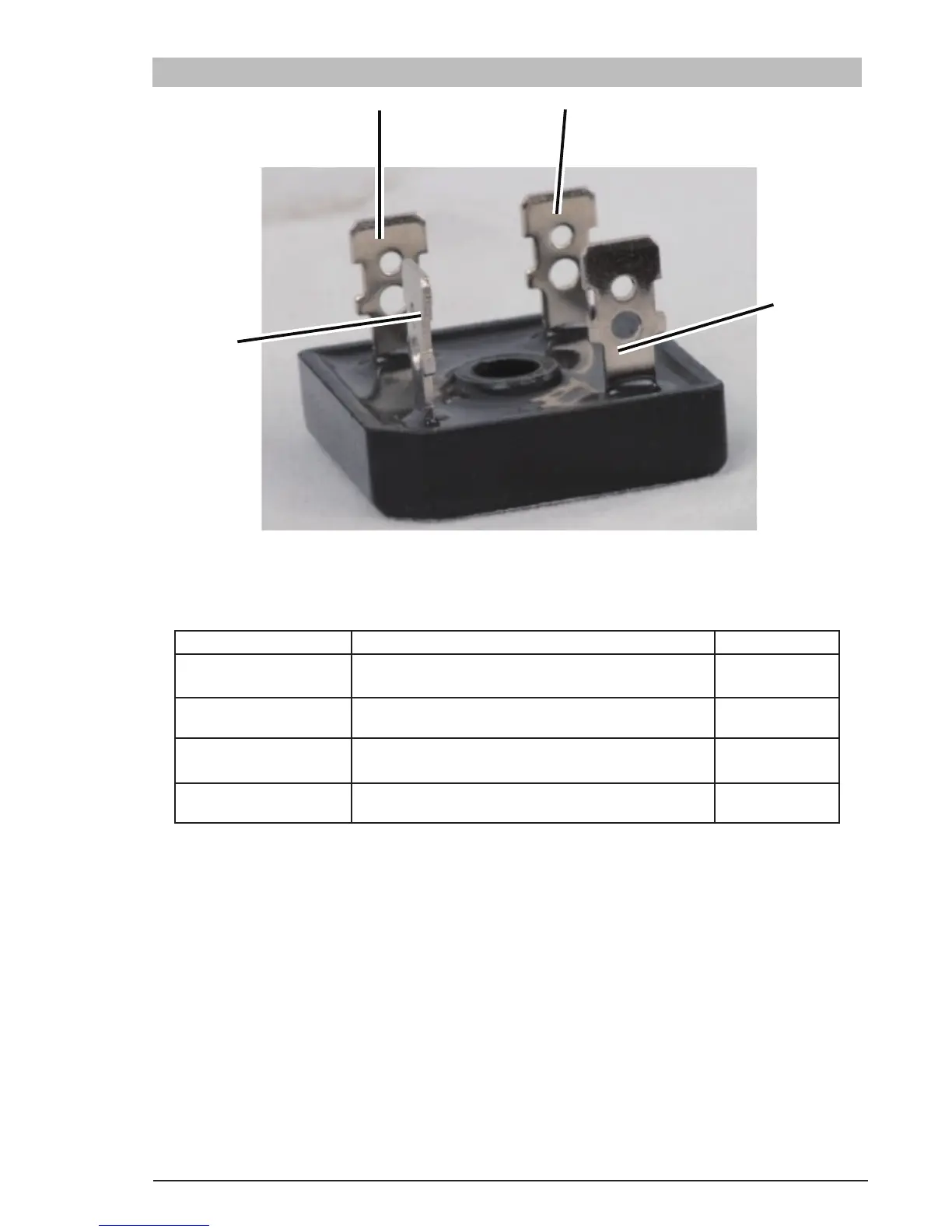
6.10 Check Main Input Rectifier
AC2
DC+
Art # A-10291
Figure 6-8 Main Input Rectifier
Remove the main input rectifier from the heatsink and start the testing.
Input Rectifier Testing Multimeter Lead Placement Diode Voltage
AC1 to DC+
Positive meter lead to AC1
Negative meter lead to TP DC+
0.2 – 0.8 VDC
AC2 to DC+
Positive meter lead to AC2
Negative meter lead to TP DC+
0.2 – 0.8 VDC
AC1 to DC-
Positive meter lead to TP DC-
Negative meter lead to TP AC1
0.2 – 0.8 VDC
AC2 to DC-
Positive meter lead to TP DC-
Negative meter lead to TP AC2
0.2 – 0.8 VDC
Table 6-4 Input Rectifier, Multimeter Set to Measure Diode Voltage
Measurements may be made directly onto the main input rectifier. AC1 and AC2 may be measured from the pins
on the mains supply plug with the main power switch set to the ON position.