Troubleshooting 6-12 Manual 0-5230
CUTMASTER 10MM, 12MM TROUBLESHOOTING
6.11 DC Bus Voltage Measurement
Apply voltage to the Power Source.
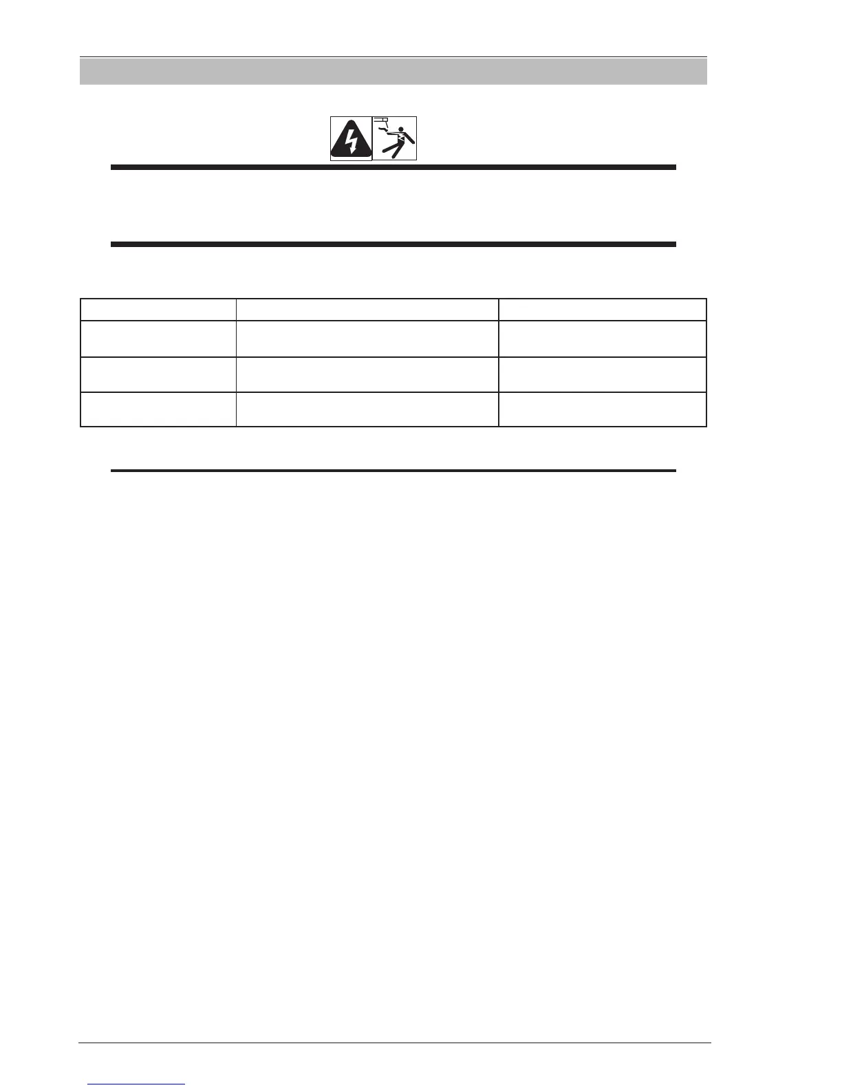
Warning
There are extremely dangerous voltage and power levels present inside this Power Source. Do not attempt to diagnose or
repair unless you have had training in power electronics measurement and troubleshooting techniques.
Once power is applied to the Power Source, there are extremely hazardous voltage and power levels present.
Do not touch any live parts.
Refer to Figure 6-4 in Section 6.06 for Main Inverter Board.
DC Bus Testing Multimeter Lead Placement Voltage with Supply voltage ON
Upper capacitor bank
Positive meter lead to TP 30
Negative meter lead to TP 29
192 VDC +/-10%
Lower capacitor bank
Positive meter lead to TP 31
Negative meter lead to TP 32
192 VDC +/-10%
Overall capacitor bank
Positive meter lead to TP 29
Negative meter lead to TP 32
384 VDC +/-10%
Table 6-5 DC BUS, Multimeter Set to Measure DC volts
NOTE
These DC voltages are at nominal mains supply voltage of 240VAC.