TROUBLESHOOTING CUTMASTER 10MM, 12MM
Manual 0-5230 6-15 Troubleshooting
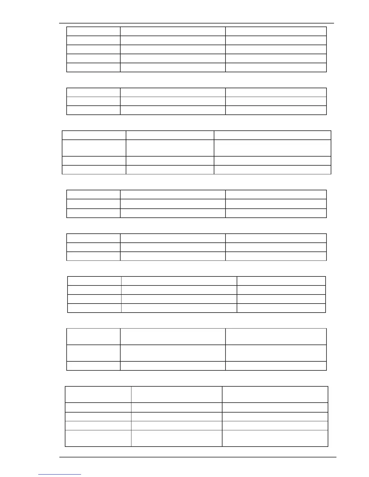
WA Header Pin Pin function Signal
1 Power source of current sensor 15VDC
2 Power source of current sensor -15VDC
3 Output current feedback
4 GND 0VDC
Table 6-12 WA Header Pin Function
FAN Header Pin Pin function Signal
1 Power source of fan 24VDC
2 0VDC(fan negative)when fan is on 0VDC
Table 6-13 FAN Header Pin Function
Transf IFB Header Pin Pin function Signal
1 Pilot ARC current feedback signal -0.8VDC
+5VDC( A main cutting arc is established)
2 GND 0VDC
3 N/A N/A
Table 6-14 Transf IFB Header Pin Function
WV Header Pin Pin function Signal
1 Positive of voltage feedback Machine output +
2 Negative of voltage feedback Machine output _
Table 6-15 WV Header Pin Function
D_port Header Pin Pin function Signal
1 +12VDC +12VDC
2 Pilot ARC IGBT drive signal
Table 6-16 D_port Header Pin Function
OT Header Pin Pin function Signal
1 N/A N/A
2 Thermostat (0VDC when thermostat closed)
3 GND 0VDC
Table 6-17 OT Header Pin Function
PRESSURE Header
Pin
Pin function Signal
1 Pressure switch signal Pressure switch(0dc when switch
closed otherwise 4VDC)
2 GND 0VDC
Table 6-18 PRESSURE Header Pin Function
GUN& TEST Header Pin Pin function Signal
1 GND 0VDC
2 Gun switch signal 0VDC when switch ON otherwise 27VDC
3 Cup test signal 0VDC
4 Cup test signal 0VDC when the cup is fixed otherwise
27VDC
Table 6-19 GUN& TEST Header Pin Function
 Loading...