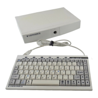
PAGE 80 VIDEONICS TITLEMAKER 3000
INSTRUCTIONSFORMAKINGREMOTETRIGGERBUTTON
Tools required:
• A soldering iron and solder
• Wire cutters
• An electric drill.
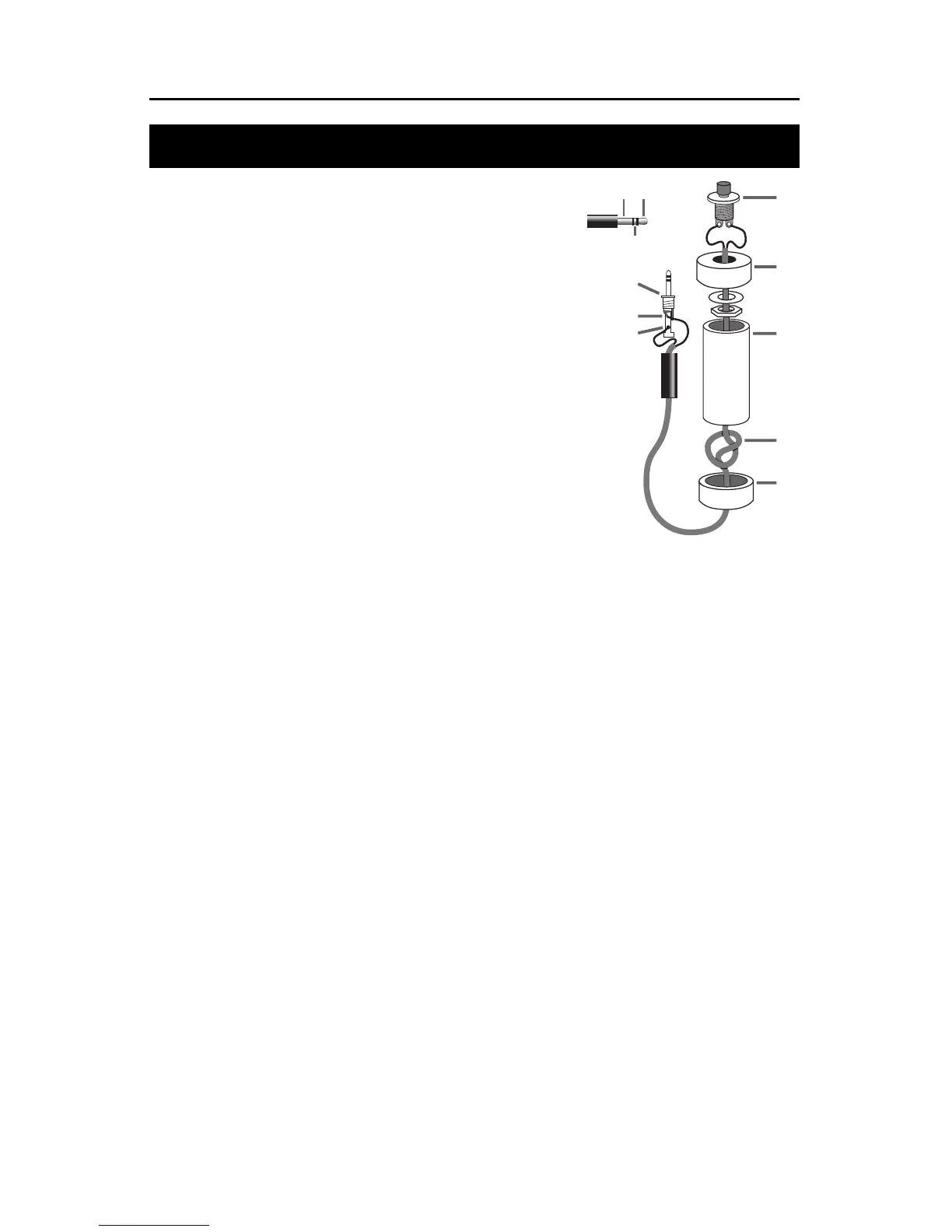
Parts required:
• A 4-inch piece of 3/4-inch PVC pipe ( C) and two end caps (B and E)
• 3-conductor, 22-24 gauge stranded wire cable (D)
• A “normally open momentary push-button switch” (A)
• A stereo 3.5-mm mini-pin plug (F )
Instructions:
Drill a 1/4-inch hole in the center of one PVC end cap ( E ) and a hole to
match the push-button switch in the other end cap (B). Feed one end
of the cablethroughthe end cap with the 1/4-inch hole(E)andstrip the
ends of each wire. Tie a single knot ( D) about 8 inches from the end of
the wire. Slide the wire through the PVC pipe, the nut and washer, and
the other end cap (B). Solder the two wires at the knotted end to the
two poles on the switch (A). Slip the switch into the end cap and
secure it using the nut and washer.
Solder the other ends of the cable to the plug (F). Connect to the tip
(G) and the base (H) of the plug. Don’t connect anything to the middle
section of the plug (X ). Push the end caps in place. After testing, you
can glue the end caps usingPVCcement,ifyou wish. Solder the wires at the other end of the cord to the
poles from thetipandbase of the stereo mini-pin plug. Ifyou’reunsurewhich poles are which, ask at the
store when you make the purchase. Your new remote trigger plugs into the “GPI (CONTROL)” jack on
the back of TitleMaker 3000.
IMPORTANT! Any time you plug or unplug the GPI trigger, make sure TitleMaker 3000 is turned
OFF. Plugging or unplugging with the unit turned on can cause the loss of your work.
F
A
C
D
G
H
B
E
✖
GH