3. POWERMASTER-10 G2 INSTALLATION
D-303222 PowerMaster-10/30 G2 Installer's Guide 9
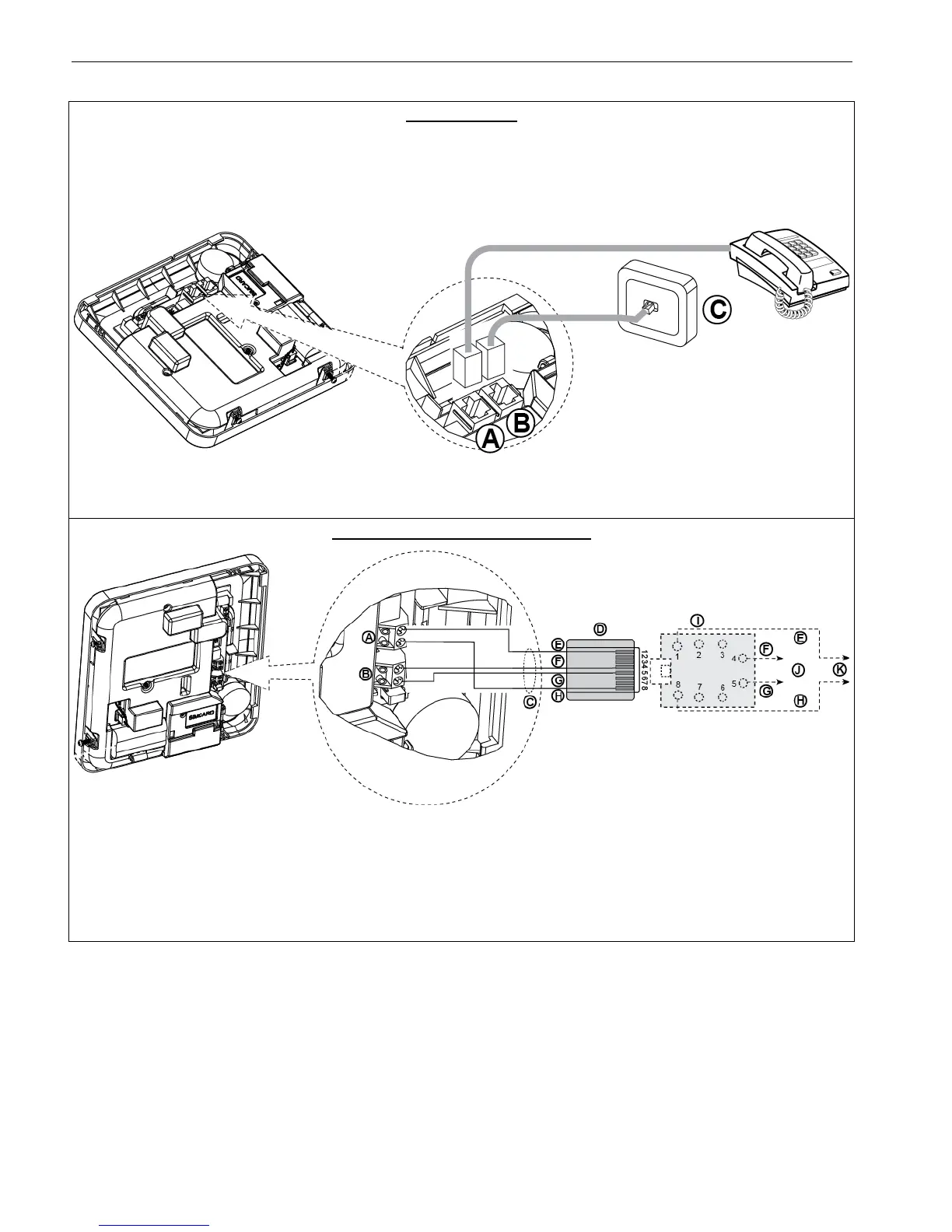
3.2 Connecting to the Telephone Line
PHONE WIRING
Connect the telephone cable to the SET connector and connect the telephone line cable to the LINE connector
(through the desired wiring cable entry).
Notes:
1. The telephone cable should be no longer than 3 meters.
2. For UL installations, the telephone cable must be no less than 26 AWG.
A. SET
B. LINE
C. Tel line wall jack
PHONE WIRING IN NORTH AMERICA
D. 8-position RJ-31X plug
Figure 3.2 –Phone Wiring
This equipment is designed to be connected to the telephone network using an RJ11 connector which complies with
Part 68 rules and requirements adopted by ACTA and a properly installed RJ31X connector. See drawing above for
details.
In the case that RJ31X is not available (consult your telephone company or a qualified installer), the telephone line
should be connected to the PowerMaster-10 G2 unit first and then all other home equipment should be connected to
the PowerMaster-10 G2 "Phone" outlet.

 Loading...


