3. POWERMASTER-10 G2 INSTALLATION
10 D-303222 PowerMaster-10/30 G2 Installer's Guide
3.3 System Planning & Programming
Program the system now as instructed in the programming section.
The tables in APPENDIX C will help you plan and record location of each detector, the holder and assignment of each
transmitter.
3.4 GSM Module Installation
The internal GSM 350 module enables the PowerMaster-10 G2 system to operate over a GSM/GPRS cellular network
(for further details, see the GSM 350 PG2 Installation Instructions).
The GSM modem auto detection feature enables automatic enrollment of the GSM modem into the PowerMaster-10
G2 control panel memory. GSM modem auto detection is activated in one of two ways: after tamper restore and after
reset (power-up or after exiting the installer menu). This causes the PowerMaster-10 G2 to automatically scan GSM
COM ports for the presence of the GSM modem.
In the event that the GSM modem auto detection fails and the modem was previously enrolled in the PowerMaster-10
G2 control panel, the message "Cel Remvd Cnfrm" will be displayed. This message will disappear from the display only
after the user presses the button. The modem is then considered as not enrolled and no GSM trouble
message will be displayed.
Notes:
1) A message is displayed only when the PowerMaster-10 G2 alarm system is disarmed.
2) The GSM Alarm Transmission System compliance with EN 50131-1 ATS4 was proven by testing the signaling
security requirements D2, M2, T3, S1, I2” detailed in EN 50136-1-1:1998/A2: 2008, EN 50136-2-1:1998/A1: 2001,
EN50136-2-2: 1998.
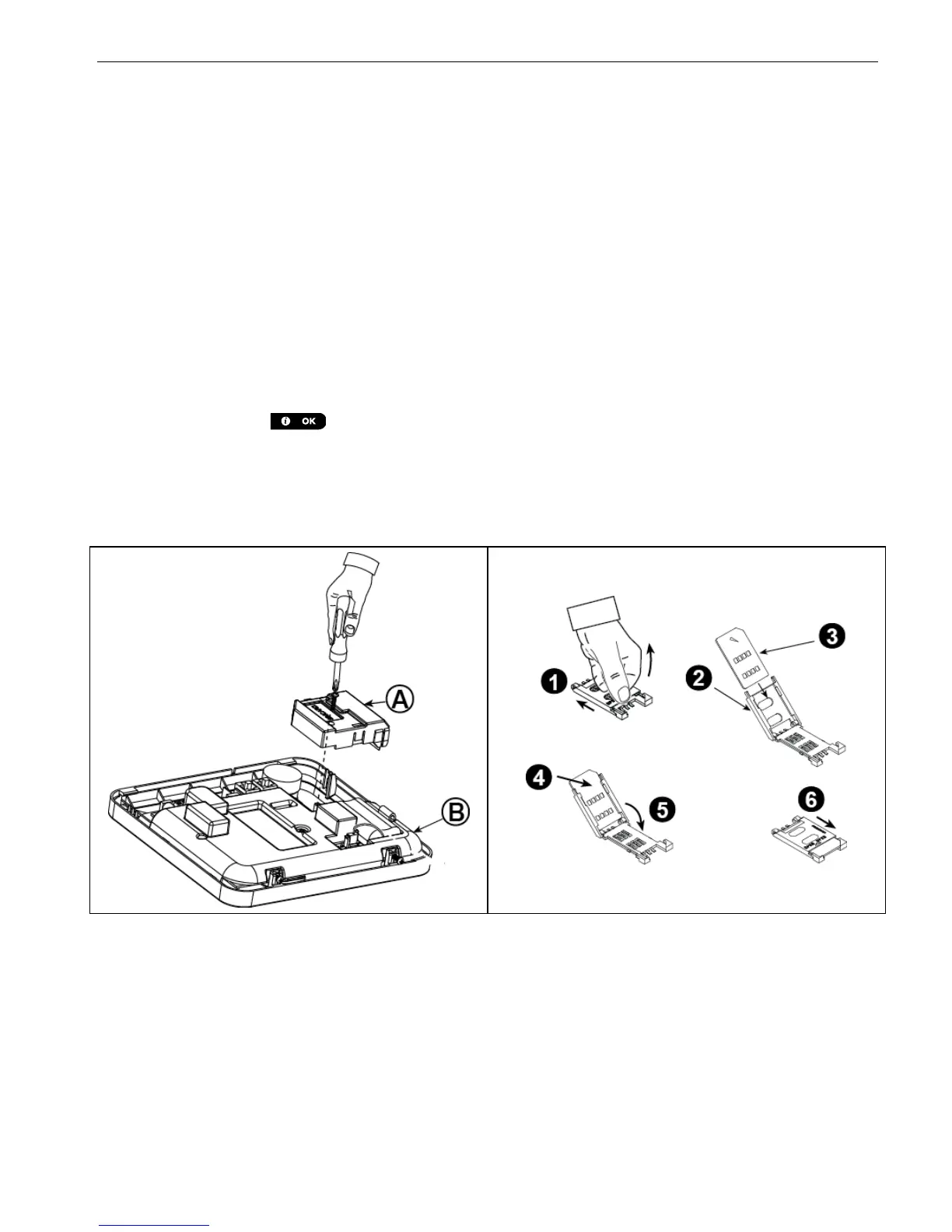
Insert the SIM card into the GSM module as shown in the
above drawing.
1. Slide top cover.
2. Open cover
3. Align SIM card in cover (note cover orientation)
4. Slide SIM card into cover
5. Rotate cover to close
6. Lock cover to close
IMPORTANT! Do not insert or remove SIM card when the
control panel is powered by AC power or battery.

 Loading...


