4. POWERMASTER-30 G2 INSTALLATION
18 D-303222 PowerMaster-10/30 G2 Installer's Guide
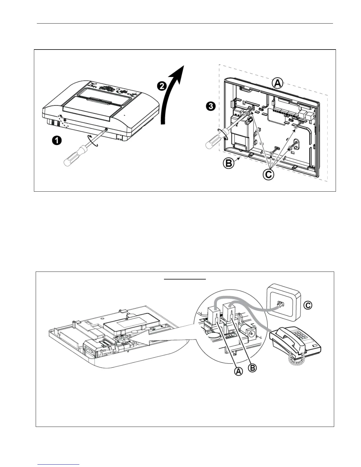
4.2 Opening the PowerMaster-30 G2 Control Panel and Bracket Mounting
To Mount the Unit:
1. Release the screws
2. Remove the front cover
3. Mark 4 drilling points on the mounting surface, then
drill 4 holes and insert wall anchors and then fasten
the back unit with 4 screws
A. Mounting surface
B. Back unit
C. Screws
Figure 4.2 – Back Unit Mounting
4.3 Connecting to the Telephone Line (detail "M" in Figure 4.1)
A. LINE B. SET C. Tel line wall jack
Connect the telephone cable to the SET connector and connect the telephone line cable to the LINE connector
(through the desired wiring cable entry).
Notes:
1. The telephone cable should be no longer than 3 meters.
2. For UL installations, the telephone cable must be no less than 26 AWG.
Figure 4.3a – Phone Wiring

 Loading...


