3. POWERMASTER-10 G2 INSTALLATION
D-303222 PowerMaster-10/30 G2 Installer's Guide 13
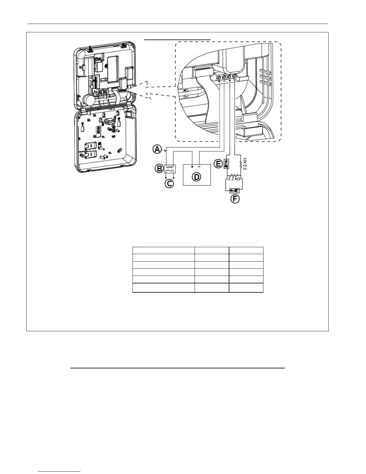
A. PGM output
Vmax=30v
Imax=100mA
B. Relay
C. Device
D. External power supply 5 -
30VDC
E. Wired detector's Tamper
F. Wired detector's alarm or
Arming Key (see section
5.4.2, “Zone Type List”
table).
For UL installations, D and E
must be UL listed.
Note:
The wired detector should be installed at least 2 meters away from the
control panel.
Regarding the wired zone, the control panel classifies the events according
to the resistance it measures as shown in the table below.
E.O.L or Arming Key Resistance
Notes:
1. The E.O.L resistors are 2.2 kΩ resistors of 1/4 W, 5% supplied with the
panel and are UL listed under the name EOLR-3, kit number 57000850.
2. If the Arming Key is enabled, the wired zone must be located in the
protected area.
Figure 3.6b – PGM & Zone Wiring
3.7 Connecting Power to the Control Panel
CONNECTING AC POWER TO CONTROL PANEL USING AC/AC TRANSFORMER
Connect the power cable and close the control panel as shown below.
Notes:
1) Do not use mains cable (3 m long) or power supply other than that supplied by the manufacturer DONGGUAN
ORIENTAL HERO ELE. CO. LTD., model no. OH-41111AT-2.
2) For UL installations (UL), the plug-in transformer must have restraining means. For Canada (CUL), it cannot have
restraining means.
Note: This equipment should be installed in accordance with Chapter 2 of the National Fire Alarm Code, ANSI/NFPA 72 and
CAN/ULC-S540.

 Loading...


