4. POWERMASTER-30 G2 INSTALLATION
22 D-303222 PowerMaster-10/30 G2 Installer's Guide
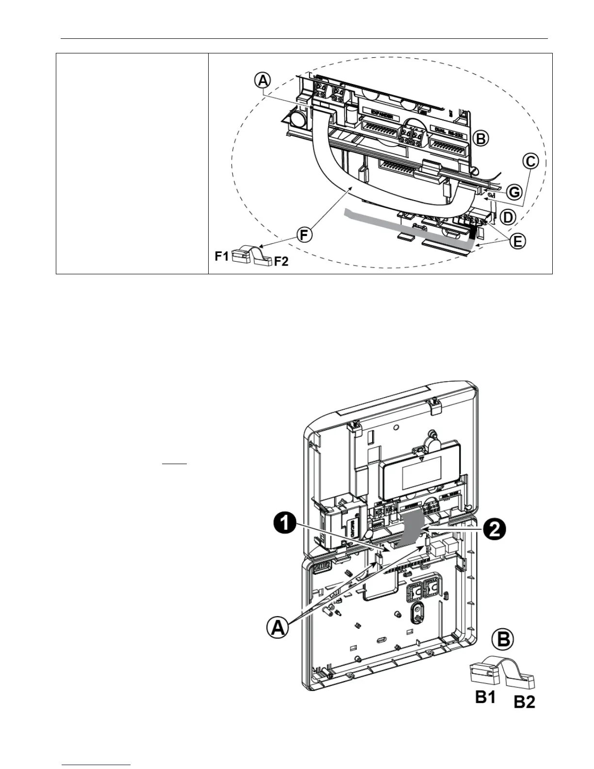
A. PowerMaster-30 G2 connector
B. Front unit
C. PGM-5 Module
D. Back unit
E. Wiring Cable
F. Flat cable
F1. This side for front unit
F2. This side for back unit
G. PGM-5 flat cable receptacle
Figure 4.8 – PGM-5 Module Mounting
4.9 Optional Expander Module (detail "K" in Figure 4.1)
The Expander module is an optional module. If this optional module is used, the wired zone or special siren on the front
panel should not be used.
Note: The optional Expander Module not to be connected in UL Listed product.
Mount the Expander module as shown in Figure 4.9a.
1. Press downward on the Expander module
(located in the back panel) between its 2
clips.
2. Connect the Expander module flat cable
to the front panel Expander receptacle.
Caution! The receptacle with strain relief
clip is for the front unit – do not connect it to
the back unit!
A. 2 clips
B. Flat cable with one strain relief clip
B1. This side for front unit
B2. This side for back unit
Figure 4.9a –Expander Module

 Loading...


