4. POWERMASTER-30 G2 INSTALLATION
D-303222 PowerMaster-10/30 G2 Installer's Guide 23
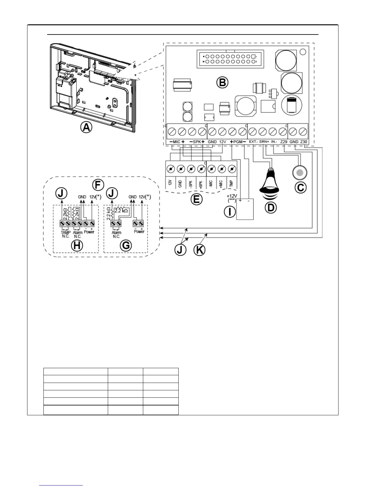
OPTIONAL EXPANDER MODULE, ZONES, SIRENS, AUDIO BOX AND WIRED DETECTORS WIRING
A. Back Unit
B. Expander
C. Internal siren or strobe 6-12 VDC,
150 mA Max.
D. External siren MG441PDS or similar siren 12 VDC
(nominal) 350 mA Max.
E. Voice box
F. Connect wired detectors as illustrated.
Note:
The wired detector should be installed at least 2
meters away from the control panel.
Regarding the two wired zones, the control panel
classifies the events according to the resistance it
measures as shown in the table below.
E.O.L or Arming Key Resistance
Notes:
1. The E.O.L resistors are 2.2 kΩ resistors of 1/4 W,
5% supplied with the panel and are UL listed
under the name EOLR-3, kit number 57000850.
2. If the Arming enabled is set, the wired zone must
be located in the protected area.
G. Detector without tamper switch or Arming Key (see
section 5.4.2, “Zone Type List” table).
H. Detector with tamper switch or arming key's tamper
I. PGM device
J. Wired zone A or B
K. Ground (GND)
Figure 4.9b – Zone
and Siren Wiring
Notes for EXPANDER module wiring:
* Wired zone
terminals can be connected to a normally closed contact of a detector, switch (for example a Tamper
switch of any device), or a pushbutton, via a 2.2 K
resistor. The 12V terminal can be used to supply 12V (up to
36mA) to a detector (if necessary).
** The EXT terminal can be used to trigger an external siren.
The INT terminal can be programmed for an "internal siren" or "strobe" (see par. 5.7).

 Loading...


