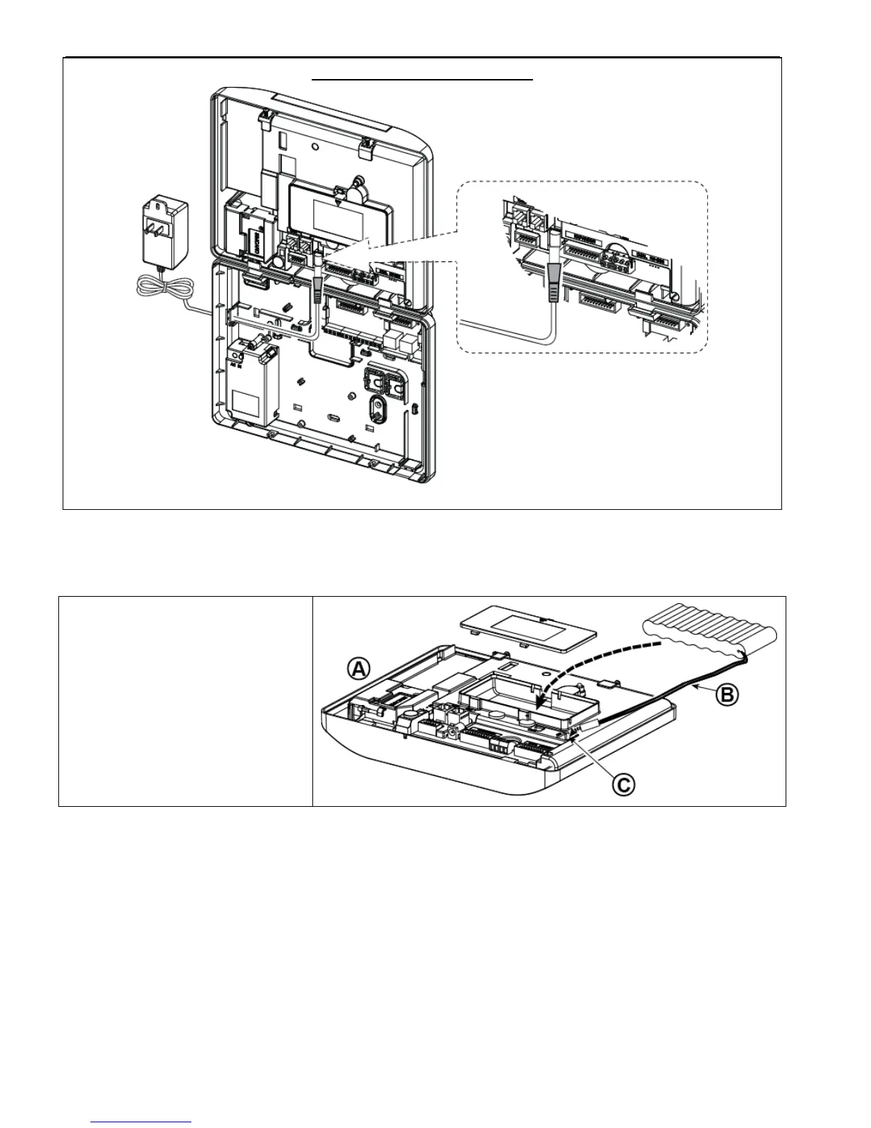
Open battery compartment cover.
Insert one 6-battery pack or 8-battery
pack and connect its connector as
shown in Figure 4.11.
A. Front unit
B. Battery cable
C. Battery cable connector
Figure 4.11 – Battery Insertion
4.12 Supplying Power to the Unit
Connect power to the PowerMaster-30 G2 temporarily (see Figure 4.10). Alternatively, you may power up from the
backup battery, as shown in Figure 4.11.
Disregard any “trouble” indications pertaining to lack of battery or lack of telephone line connection.
For Europe Safety Compliance:
a. The model shall be installed according to the local electrical code.
b. The circuit breaker shall be readily accessible.
c. The rating of the external circuit breaker shall be 16A or less.
Please refer to Figure 4.11 "Battery Insertion".

 Loading...


