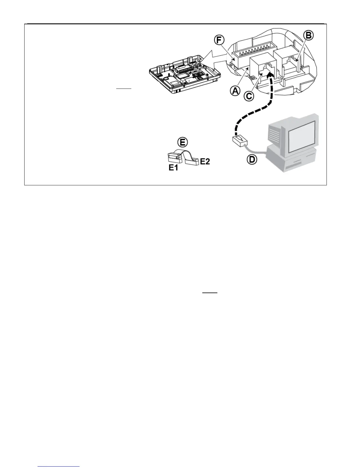
1. To install the DUAL RS-232 module into
the control panel, press it into the
marked location (see Figure 4.7) until a
click is heard.
2. Connect the flat cable (included in the
module's package) between the front
panel and the DUAL RS-232 receptacle.
Caution! The receptacle with strain
relief clip is for the front unit – do not
connect it to the back unit!
3. Connect a local PC to the DUAL RS-
232 module connector (B) or (C), as
shown in Figure 4.7.
A. DUAL RS-232 Module
B. Connector for PC
C. Connector for PC
D. Visonic PC cable
E. Flat cable with one strain relief clip
E1. This side for front unit
E2. This side for back unit
F. Flat cable connector
Figure 4.7 –Dual RS-232 Module Mounting
4.8 PGM-5 Installation (located instead of detail "F" in Figure 4.1)
PGM-5 is an output interface module designed to provide alarm, trouble events and status signals to external devices
such as long range wireless monitoring transmitters, CCTV systems, home-automation systems and LED annunciation
panels (for further details see the PGM-5 Installation Instructions).
The PGM-5 provides 5 solid state relay contact outputs and is designed to be used as a plug-in internal add-on module
with the PowerMaster-30 G2 control panel.
Mount the PGM-5 module as shown in Figure 4.8.
1. Press downward on the PGM-5 module (D), located in the back panel, between its 2 clips.
2. Connect the PGM-5 module flat cable (F) to the front panel PGM-5 receptacle and to the flat cable receptacle of
the PGM-5 (G).
Caution! The connector with strain relief clip (F1) is for the front unit – do not connect it to the back unit!
Notes:
i) The PGM-5 will be active only if the PGM-5 option was enabled in the factory default of the control panel.
ii) For wiring instructions, refer to the PGM-5 Installation Instructions included in the module's package.
iii) PGM-5 plug-in module not evaluated by UL.
Caution! When mounting the PGM-5 module it is strongly recommended to route the wiring cable (E) as shown in
Figure 4.8) to prevent interference which may occur if routed too close to the control panel antennas.

 Loading...


