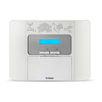
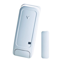
3. POWERMASTER-10 G2 INSTALLATION
14 D-303222 PowerMaster-10/30 G2 Installer's Guide
Notes for UL installations:
1. A device that is connected to PGM terminal should not be programmed to be activated during standby.
2. The system shall be installed in accordance with CSA C22.1 Canadian Electrical Code, Part 1.
3. A minimum spacing of 1/4 inch shall be maintained between the telephone wiring and the low voltage wiring (zones,
bell circuit, etc.). Do not route the LINE and SET wires in the same wiring channel with other wires.
4. Do not connect to a receptacle controlled by a switch.
5. Hard wired zones are for BURG use only.
6 Tamper (E) and external power supply (D) must be UL Listed.

 Loading...


