EasyManuals Logo

Visonic POWERMASTER-10 - INSTALLER GUIDE User Manual

Visonic POWERMASTER-10 - INSTALLER GUIDE
86 pages
To Next Page IconTo Next Page
To Previous Page IconTo Previous Page
Page #10 background imageLoading...
Page #10 background image
D-302756 9
Gather up all transmitters and detectors used in the system and mark each one in accordance with your
deployment plan.
Program the system now, before mounting, as instructed in the programming section.
3.3 Mounting the Unit
Required tool: Philips screwdriver #2.
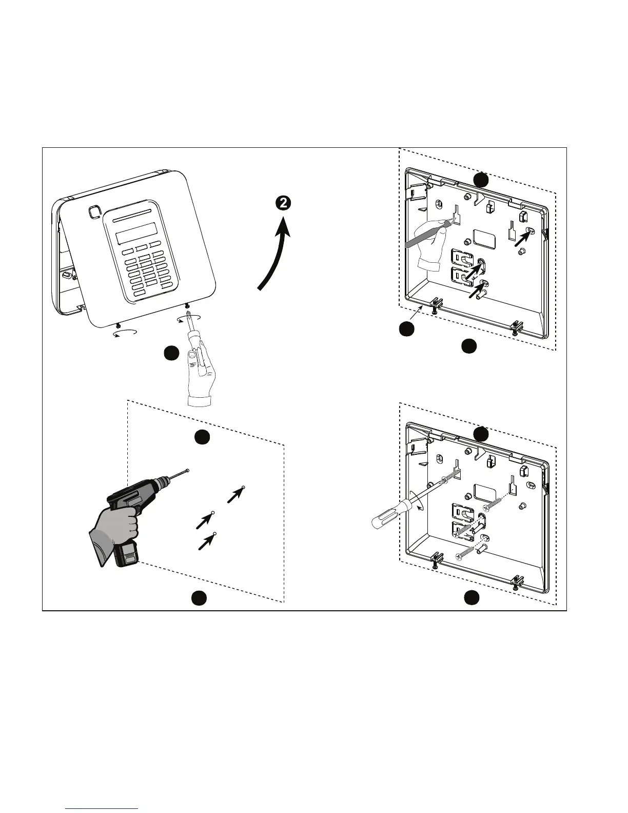
PowerMaster-10 mounting process is shown in Figure 3.3 - 3.4.
4
3
5
1
A
A
A
B
A. Mounting surface
B. Back unit
To Mount the Unit:
1. Release the screws
2. Remove the front cover
3. Mark 4 drilling points on the mounting surface
4. Drill 4 holes and insert wall anchors
5. Fasten the back unit with 4 screws
Figure 3.3 – Back Unit Mounting
WARNING! When plugging SIREN & ZONE terminals back into place, be sure to align them carefully with the
pins on the PCB. Misaligned or reverse insertion of terminals may damage internal PowerMaster-10 circuits!

Table of Contents

Questions and Answers:

Question and Answer IconNeed help?

Do you have a question about the Visonic POWERMASTER-10 - INSTALLER GUIDE and is the answer not in the manual?

Visonic POWERMASTER-10 - INSTALLER GUIDE Specifications

General IconGeneral
CategorySecurity System
ModelPOWERMASTER-10
Wireless ProtocolPowerG
Backup BatteryYes
User CodesUp to 48 user codes
TypeWireless Alarm System
Partitions3
CommunicationGSM
Wireless Frequency868 MHz
KeypadsUp to 8 keypads
Event Log1000 events
Power SupplyExternal power supply
Backup Battery Voltage7.2V
Operating Temperature-10°C to +50°C
Humidity85% non-condensing
ZonesUp to 30 wireless zones

Related product manuals