D-302756 79
Trouble
Event Fuse
Fail
Fuse
Restore
Jamming Jamming
Restore
AC
Failure
AC
Restore
CPU
Low
Battery
CPU Low
Battery
Restore
CP
Tamper
1
st
digit 2 2 2 2 1 1 1 1 1
2
nd
digit C D E F 1 2 3 4 6
Event CP Tamper
Restore
No Active COMM. &
LINE Restore
Enter Test Exit Test Auto Test
1
st
digit 1 1 1 1 1 1
2
nd
digit 7 8 A D E F
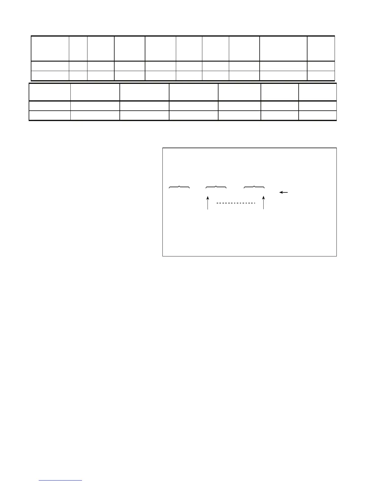
B4. Understanding the Scancom Reporting Protocol Data Format
The SCANCOM data format consists of 13
decimal digits divided into 4 groups, from left to
right, as shown at the right side.
Each channel is associated with a specific
event as follows:
1
st
"C": Fire
2
nd
"C": Personal attack
3
rd
"C": Intruder
4
th
"C": Open/close
5
th
"C": Alarm cancel
6
th
"C": Emergency
7
th
"C": Second alarm
8
th
"C": Trouble messages
aaaa cccc cccc s
Account
Code
Channels
1 - 4
Channels
5 - 8
System Status:
no trouble,
test, low battery
The digit in this position conveys
the status of channel 1
The digit in this position conveys
the status of channel 8
Scancom Data Format