68 D-302756
See the table below for a complete list of possible GSM/GPRS
messages.
∗ If there are no wireless devices enrolled in the PowerMaster-10
system, the PowerMaster-10 display reads "
NO DEVICES
".
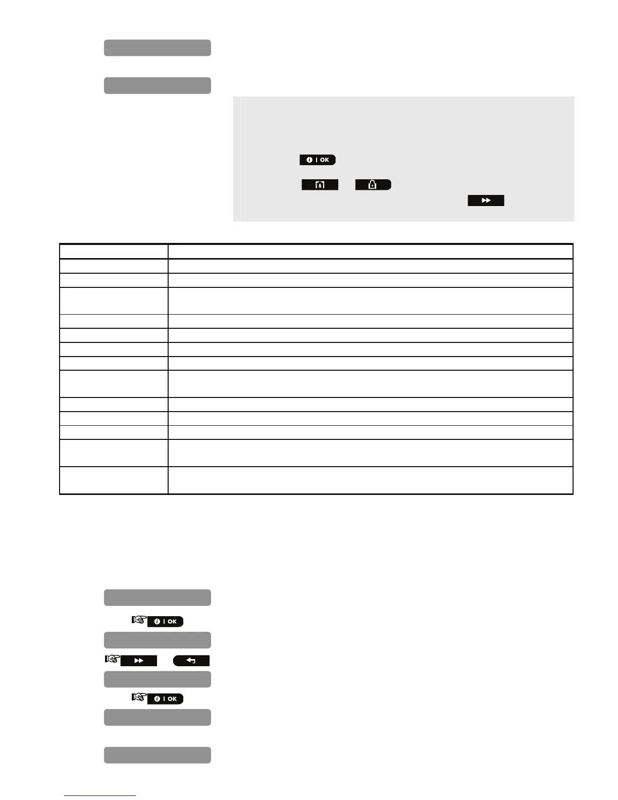
** When the button is pressed the test result takes up to 4 min.
before it is displayed, depending on the severity of the failure.
Pressing the or buttons at any stage in the procedure
will take you to “
<OK> TO EXIT
” or pressing the
button at the
end of the procedure will take you to the "
LAN
" menu.
The following GSM/ GPRS messages are reported:
Message Description
Unit is OK GSM / GPRS is functioning correctly.
GSM comm. loss The GSM/GPRS module does not communicate with the Panel
Pin code fail Missing or wrong PIN code.
(Only if SIM card PIN code is enabled.)
GSM net. fail Unit failed with registration to local GSM network.
SIM card fail SIM not installed or SIM card failure.
GSM not detected GSM auto enroll failed to detect GSM/GPRS module.
No GPRS service The SIM card does not have the GPRS service enabled.
GPRS conn. fail Local GPRS network is not available or, wrong setting to GPRS APN, user and/or
password.
Srvr unavailable IPMP Receiver cannot be reached – Check the Server IP
IP not defined Server IP #1 and #2 are not configured.
APN not defined APN is not configured.
SIM card locked After entering a wrong PIN code 3 consecutive times the SIM is locked. To unlock it
enter a PUK number. The PUK number cannot be entered by the PowerMaster-10.
Denied by server The IPMP denies the connection request. Check that the Panel is registered to the IPMP
Receiver.
5.1.6 LAN Connection Test
The LAN Connection diagnostic procedure tests PowerLink Broadband Module communication to the IPMP and
reports the diagnostic result. In case of communication failure, detailed information of the failure is reported.
Note: If the PowerLink Broadband Module is not registered to the PowerMaster-10, the menu "
LAN
CONNECT.TEST
" will not be displayed.
1.
Repeat steps 1 to 4 of section 4.2 "Entering the Installer Menu".
2.
*
3.
or
4.
**
UNIT IS OK
PLEASE WAIT…
LAN
WL DEVICES
DIAGNOSTICS
UNIT IS OK
PLEASE WAIT…

 Loading...


