Connecting to the nitrogen gas supplyB-19
Gas and exhaust connections
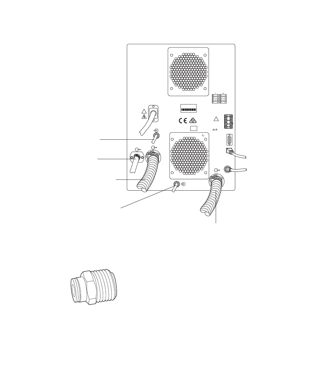
5. Attach a nitrogen regulator (not provided) to the nitrogen supply.
6. Install the 6-mm stud into the regulator outlet.
7. Connect the free end of the long piece of 6-mm PTFE tubing to the 6-mm
stud.
RP00012
01757 U.S.A.
!
!
V ~ 200 - 240V ~ 200 - 240
Hz 50 - 60Hz 50 - 60
VVA 900
ACN 065444751
1
2
3
4
5
6
7
8
9
10
Analog
Not used
Stop Flow
Switch 2
Ground
Ground
Out
Out
1
2
3
4
5
6
7
8
9
10
Inject Start
Event
Switch 3
Switch 4
Ground
Ground
In
In
Out
Out
Out
RS 232RS 232
ETHERNETETHERNET
API GasAPI Gas
COLLISION GASCOLLISION GAS
6.9 Bar Maximum6.9 Bar Maximum
1.0 BAR MAXIMUM1.0 BAR M AXIMUM
SOURCE VENTSOURCE VENT
VACUUMVACUUM
VACUUMVACUUM
IVDIVD
PUMPPUMP
Serial Number
Source vent
Nitrogen inlet
Collision cell gas inlet
Source vacuum connection
Turbo-pump vacuum
connection