Watlow PM PLUS™ 6 • 119 • Chapter 10 Appendix
Modbus
®
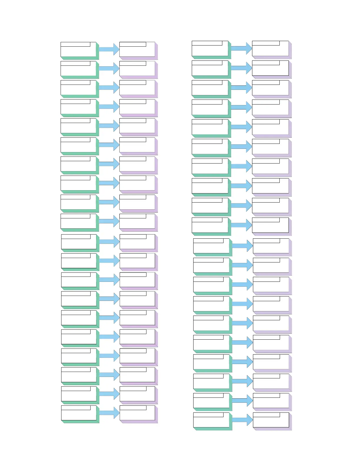
Map 1 Default Assembly Structure 40-119
Pointer 1 = 1880 & 1881
Loop, Control Mode
Registers 40 & 41
Registers 200 & 201
Registers 42 & 43
Registers 202 & 203
Registers 44 & 45 Registers 204 & 205
Registers 46 & 47
Registers 206 & 207
Registers 48 & 49
Registers 208 & 209
Registers 50 & 51 Registers 210 & 211
Registers 52 & 53 Registers 212 & 213
Registers 54 & 55 Registers 214 & 215
Registers 56 & 57
Registers 216 & 217
Registers 58 & 59 Registers 218 & 219
Value of Pointer 1
Pointer 2 = 2160 & 2161
Set Point
Value of Pointer 2
Pointer 3 = 2162 & 2163
Manual Power
Value of Pointer 3
Pointer 4 = 1480 & 1481
Alarm 1 High Set Point
Value of Pointer 4
Pointer 5 = 1482 & 1483
Alarm 1 Low Set Point
Value of Pointer 5
Pointer 6 = 1530 & 1531
Alarm 2 High Set Point
Value of Pointer 6
Pointer 7 = 1532 & 1533
Alarm 2 Low Set Point
Value of Pointer 7
Pointer 8 = 1580 & 1581
Alarm 3 High Set Point
Value of Pointer 8
Pointer 9 = 1582 & 1583
Alarm 3 Low Set Point
Value of Pointer 9
Pointer 10 = 1630 & 1631
Alarm 4 High Set Point
Value of Pointer 10
Assembly Pointer
Registers
Assembly Working
Addresses
Pointer 11 = 1632 & 1633
Alarm 4 Low Set Point
Registers 60 & 61
Registers 220 & 221
Registers 62 & 63
Registers 222 & 223
Registers 64 & 65 Registers 224 & 225
Registers 66 & 67
Registers 226 & 227
Registers 68 & 69
Registers 228 & 229
Registers 70 & 71
Registers 230 & 231
Registers 72 & 73
Registers 232 & 233
Registers 74 & 75
Registers 234 & 235
Registers 76 & 77
Registers 236 & 237
Registers 78 & 79
Registers 238 & 239
Value of Pointer 11
Pointer 12 = 2540 & 2541
Profile Action Request
Value of Pointer 12
Pointer 13 = 2520 & 2521
Profile Start
Value of Pointer 13
Pointer 14 = 1890 & 1891
Heat Proportional Band
Value of Pointer 14
Pointer 15 = 1892 & 1893
Cool Proportional Band
Value of Pointer 15
Pointer 16 = 1894 & 1895
Time Integral
Value of Pointer 16
Pointer 17 = 1896 & 1897
Time Derivative
Value of Pointer 17
Pointer 18 = 1900 & 1901
On/Off Heat Hysteresis
Value of Pointer 18
Pointer 19 = 1902 & 1903
On/Off Cool Hysteresis
Value of Pointer 19
Pointer 20 = 1898 & 1899
Deadband
Value of Pointer 20
Pointer 21 = 360 & 361
Analog Input 1
Value
Registers 80 & 81
Registers 240 & 241
Registers 82 & 83
Registers 242 & 243
Registers 84 & 85
Registers 244 & 245
Registers 86 & 87
Registers 246 & 247
Registers 88 & 89
Registers 248 & 249
Registers 90 & 91
Registers 250 & 251
Registers 92 & 93
Registers 252 & 253
Registers 94 & 95
Registers 254 & 256
Registers 96 & 97
Registers 256 & 257
Registers 98 & 99
Registers 258 & 259
Value of Pointer 21
Pointer 22 = 362 & 363
Analog Input 1 Error
Value of Pointer 22
Pointer 23 = 440 & 441
Analog Input 2
Value
Value of Pointer 23
Pointer 24 = 442 & 443
Analog Input 2 Error
Value of Pointer 24
Pointer 25 = 1496 & 1497
Alarm 1 State
Value of Pointer 25
Pointer 26 = 1546 & 1547
Alarm 2 State
Value of Pointer 26
Pointer 27 = 1596 & 1597
Alarm 3 State
Value of Pointer 27
Pointer 28 = 1646 & 1647
Alarm 4 State
Value of Pointer 28
Pointer 29 = 1328 & 1329
Digital Input 5 Status
Value of Pointer 29
Pointer 30 = 1348 & 1349
Digital Input 6 Status
Value of Pointer 30
Assembly Pointer
Registers
Assembly Working
Addresses
Pointer 31 = 1882 & 1883
Control Mode Active
Registers 100 & 101
Registers 260 & 261
Registers 102 & 103
Registers 262 & 263
Registers 104 & 105
Registers 264 & 265
Registers 106 & 107
Registers 266 & 267
Registers 108 & 109
Registers 268 & 269
Registers 110 & 111
Registers 270 & 271
Registers 112 & 113
Registers 272 & 273
Registers 114 & 115
Registers 274 & 275
Registers 116 & 117
Registers 276 & 277
Registers 118 & 119
Registers 278 & 279
Value of Pointer 31
Pointer 32 = 1904 & 1905
Heat Power
Value of Pointer 32
Pointer 33 = 1906 & 1907
Cool Power
Value of Pointer 33
Pointer 34 = 690 & 691
Limit State
Value of Pointer 34
Pointer 35 = 2520 & 2521
Profile Start
Value of Pointer 35
Pointer 36 = 2540 & 2541
Profile Action Request
Value of Pointer 36
Pointer 37 = 2524 & 2525
Active File
Value of Pointer 37
Pointer 38 = 2526 & 2527
Active Step
Value of Pointer 38
Pointer 39 = 2528 & 2529
Active Set Point
Value of Pointer 39
Pointer 40 = 2536 & 2537
Step Time Remaining
Value of Pointer 40
 Loading...


