109
DETAILED PARAMETER DESCRIPTION
Range
[Factory Setting]
Parameter Unit Description / Notes
P520 0.000...7.999
PID Proportional [ 1.000 ]
Gain 0.001
P521 0.000...9.999
PID Integral [ 1.000 ]
Gain 0.001
P522 0.000...9.999
PID Differential [ 0.000 ]
Gain 0.001
The integral gain can be defined as being the time required to change
the PI regulator output from 0 to P134, that is given, in seconds, by
the equation below:
t =
16
P521
.
P525
for the following conditions:
- P040=P520=0;
- DI3 in automatic position.
P525 0.00...100.0%
The PID Setpoint [ 0.00 ]
0.01%
Provides the setpoint (reference) of the process via cointrol via the
and keys for the PID regulator, provided that P221=0
(local) or P222=0 (remote) has been set to automatic mode. If it
has been set to Manual Mode, the frequency reference is given by
P121.
If P120=1 (backup active), the value of P525 is maintained at the
last set value (backup), even when the inverter is disabled or tuned
off.
P526 0.00...10.00s
Process Variable [ 0.10s ]
Filter 0.01s
It sets the time constant of the Process Variable Filter.
It is useful for noise filtering at the analog input AI1
(feedback of the process variable).
P527 0...1
PID Action [ 0 ]
-
Defines the action type of the PID regulator.
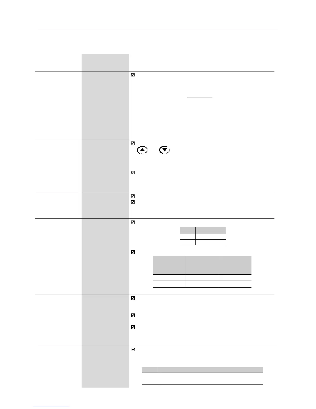
P527
0
1
Action Type
Direct
Reverse
Select it according to the table below:
For this the
motor speed
must
Increase
Increase
Process
variable
requirement
Increase
Decrease
P527 to be
used
0 (Direct)
1 (Reverse)
P528 0.00...99.9
Process Variable [ 1.00 ]
Scale Factor 0.01(<10);
0.1 (>9.99)
Defines the process variables scale. It makes the conversion between
percentage value (used internally by the inverter) and the process
variable unit.
P528 defines how the process variable at P040 will be shown:
P040=value % x P528.
Set P528 to:
P528 =
full scale of the used sensor (FM)
P234
P536 0...1
Automatic Setting [ 0 ]
of P525 -
It is posible to enable/disable the copy of P040 (PID process variable)
in P525 when the changing from manual to automatic mode using
parameter P536, that is described below.
P536
0
1
Function
Active (copies the value of P040 in P525)
Inactive (does not copies the value of P040 in P525)