108
DETAILED PARAMETER DESCRIPTION
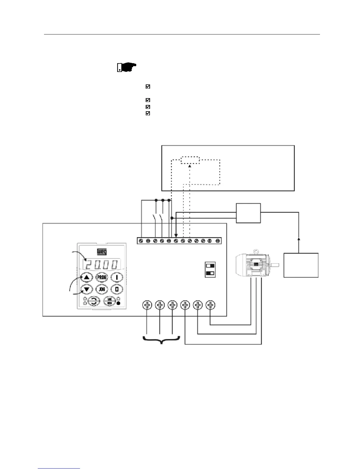
Figure 6.26 - Application example of an inverter with PID regulator
NOTE!
The inverter setting must be correct in order to obtain a good performance
of the PID regualtor. Ensure the following settings:
torque boosts (P136 and P137) and slip compensation (P138) in the
V/F control (P202=0 ou 1);
ensure that the self-tuning has been run, if in vector control (P202=2);
acceleration and deceleration ramps (P100...P103);
current limitation (P169).
CFW-08
P040
Content
Setpoint can
be changed
by the keys
X1
1 2 3 4 5 6
Line
1
2
S1
off on
123456789101112
DI1 - Gen.enable
DI3 - Manual/Auto
DI4 - Star/Stop
AI1 - Feedback
Pressure
Transducer
4-20mA
0-25 bar
0-100%
(0-25bar)
5k
≥
Setpoint via AI2 (available
with CFW-08 Plus only)
P222=2
P238=1.00
P239=0
P240=0.00
Remote mode operation (P220=1)
Setpoint via keypad.
Inverter Parametrization:
P220=1 P520=1.000
P222=0 P521=1.000
P234=1.00 P522=0.000
P235=1 P525=0
P238=0.00 P526=0.1s
P203=1 P527=0
P205=6 P528=25
Process