87
DETAILED PARAMETER DESCRIPTION
Range
[Factory Setting]
Parameter Unit Description / Notes
where:
- x = 1, 2;
- AIx is given in V or mA, according to the used signal (see
parameters P235 and P239);
- GAIN is defined by the parameters P234 and P238 for AI1
and AI2 respectively;
- OFFSET is defined by the parameters P236 and P240 for AI1
and AI2 respectively.
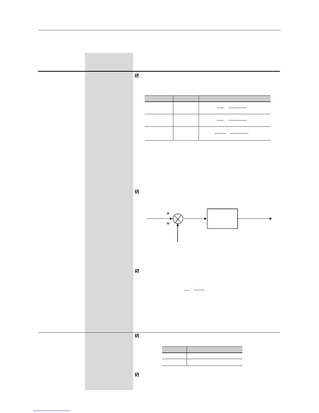
This is shown in the block diagram below:
GAIN
P234, P238
AIx'
OFFSET
(P236,P240)
P235
P239
AIx
Figure 6.18 - Block diagram of the analog inputs AI1 and AI2
Example: a 0 ... 10V signal is used (P235 = 0), AI1=5V, P234=1.00
and P236=-70%. Thus:
The motor will run in reverse direction of rotation as defined by the
commands (negative value) - if this is possible (P231=2), with a mo-
dule reference equal to 0.2 or 20% of the maximum output frequency
(P134). I.e., if P134=66.00Hz, then the frequency reference is equal
to 13.2Hz.
AI1'
=
5
+
(-70)
.
1
=
-0.2
=
-20%
10 100
[
[
P235
(1)
0...1
Analog Input AI1 [ 0 -
Signal 0...10V/0...20mA ]
-
Defines the signal type of the analog input, as shown in table below:
P235/P239
0
1
Signal type
0...10V ou 0...20mA
4...20mA
When current signals are used, change the switch position S1:1
and/or S1:2 to ON.
The internal value AIx’ that defines the frequency reference to be
used by the inverter, is given as percent of the full scale reading
and is obtained by using on of the following equations (see P235
and P239):
(
(1)
This parameter can be changed only with the inverter disabled (motor stopped).
P235/P239
0
1
2
Signal
0...10V
0...20mA
4...20mA
Equation
AIx'=
AIx
+
OFFSET
. GAIN
10 100
AIx'=
AIx
+
OFFSET
. GAIN
20 100
AIx'=
AIx-4
+
OFFSET
. GAIN
16 100
(
(
(
(
(