86
DETAILED PARAMETER DESCRIPTION
Range
[Factory Setting]
Parameter Unit Description / Notes
P230
(1)
0...2
Remote Command [ 1 - Terminals ]
Selection -
The direction of rotation is the only operation control that depends
on other parameter for operation - P231.
For more details, refer to Items 6.2.4, 6.2.5 and 6.2.6.
P231
(1)
0...2
Forward/Reverse - [ 2 - Commands]
Local/Remote Modes -
Defines the direction of rotation.
P231
0
1
2
Direction of rotation
Always forward
Always reverse
Commands as defined in
P229 and P230
P234 0.00...9.99
Analog Input AI1 [ 1.00 ]
Gain 0.01
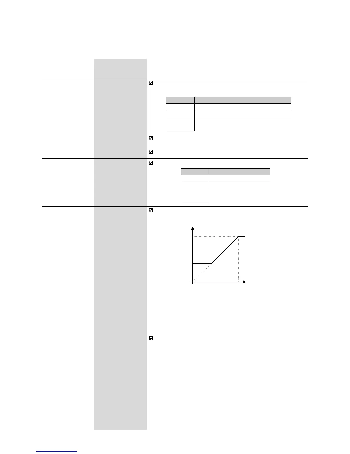
The analog inputs AI1 and AI2 define the inverter frequency reference
as shown in the curve below.
P134
P133
AI1/AI2
0
0 ..................... 100%
0 ........................ 10V (P235/P239=0)
0 ..................... 20mA (P235/P239=0)
4mA.................. 20mA (P235/P239=1)
Frequency Reference
Note that there is always a dead zone at the starting of the curve
where the frequency reference remains at the value of the
minimum frequency (P133), even when the input signal is changed.
This dead zone is only suppressed when P133=0.00.
Figure 6.17 - Determination of the frequency reference from the analog
inputs AI1 and AI2
P229
(1)
0...2
Local Command [ 0 - Keys ]
Selection -
Define the control sources for the inverter enabling disabling
FWD/REV and JOG.
(1)
This parameter can be changed only with the inverter disabled (motor stopped).
P229/P230
0
1
2
Control source
HMI-CFW08-P or HMI-CFW08-RP Keypad
Terminals (XC1)
HMI-CFW08-RS keypad
or serial interface