Operation
Operating the rear hydraulic connections 7.10
143
[en] | 05/2019 | 1000408123 | 4080T Basic Line | Operator’s Manual
7.10.2
Double-acting rear hydraulic connections
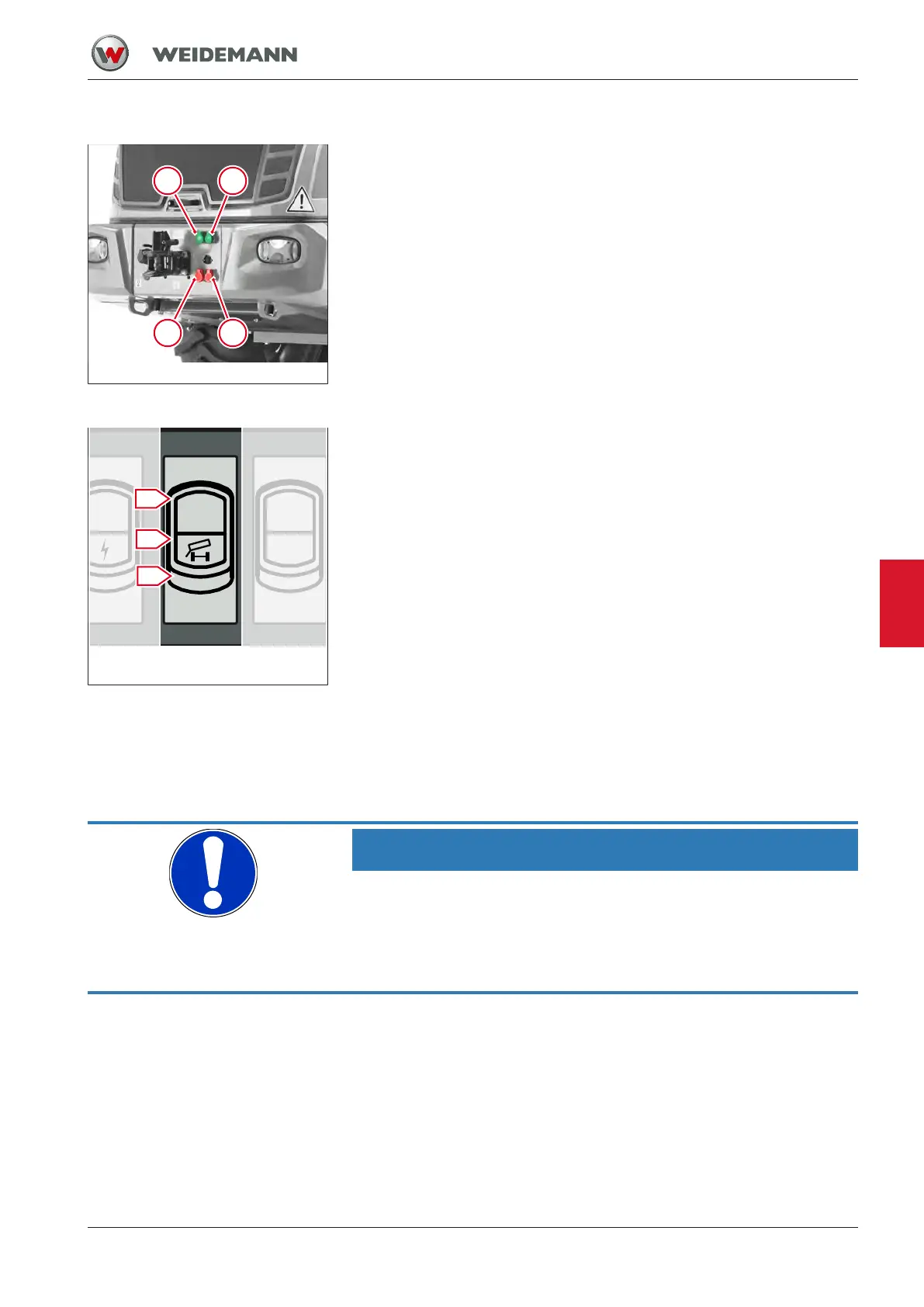
Fig.131: Rear hydraulic connections
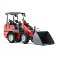
Fig.132: Operating the rear hy-
draulic connections
Operating the rear hydraulic connections 1 and 2
The rear hydraulic connections are operated with the switch in the switch
panel on the side console. The switch has three positions. When the
switch is released, it automatically switches to position 0. The hydraulic
connections are fitted with green protective caps.
▪ Move switch to position I and hold.
ð Hydraulic connection 1 is pressure side, hydraulic connection 2 is re-
turn flow.
▪ Move switch to position II and hold.
ð Hydraulic connection 1 is return flow, hydraulic connection 2 is pres-
sure side.
▪ Release switch.
ð The rear hydraulic connections are switched off.
Operating the rear hydraulic connections 3 and 4 in
continuous operation
NOTICE
Damage due to overheating of the hydraulic system!
When continuous operation is switched on and no attachment is connec-
ted, the hydraulic system overheats very quickly.
► Always bring the switch for continuous operation to the zero position
when continuous operation is not required.
7