Technical data
12.4 Electrical system
238
Operator’s Manual | 4080T Basic Line | 1000408123 | 05/2019 | [en]
12.4
Electrical system
12.4.1
Technical data
Operating voltage: 12 V
Battery: 100 Ah
Alternator: 85 A
Battery master switch: see Battery master switch on page 96
12.4.2
Fuses
The different electrical circuits are protected with fuses with different cur-
rent ratings. The fuses are located in different fuse boxes in the cab and
in the engine compartment:
• In the steering column
• The console is located to the right of the driver's seat
• In the engine compartment
• Main fuses in engine compartment
12.4.3
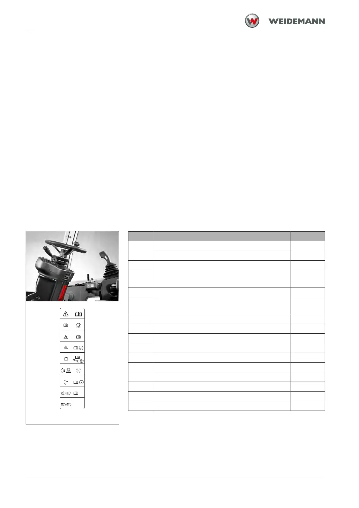
Fuses in the steering column
F10 (7,5A)
F9 (1A)
F11 (15A)
F8 (7,5A)
-
F12 (10A)
F7 (10A)
Engine
ECU
F13 (7,5A)
F6 (3A)F14 (7,5A)
F5 (15A)
F15 (15A)
F4 (15A)
F16 (15A)
F3 (7,5A)
F2 (10A)
F1 (10A)
HAZARD
STOP
L
R
L R
L R
Fig.221: Fuses in the steering
column
Item Protected function Fuse
F001 Cab 10 A
F002 Inclination switch 10 A
F003 Switch lights, display, high-current relay 7.5 A
F004 Steering column switch (window wiper), interval
relay
15 A
F005 Heating switch 15 A
F006 Display of the stability indicator (with telescopic
loader unit), DPF functions
3 A
F007 Power coupler lock, engine control unit 10 A
F008 Not assigned 7.5 A
F009 Telematic 1 A
F010 Turn indicator system 7.5 A
F011 Hazard warning system 15 A
F012 Brake lights 10 A
F013 Clearance lights, left, numberplate lights 7.5 A
F014 Clearance light, right 7.5 A
F015 Left and right low beam 15 A
F016 Left and right high beam 15 A