CYLINDER
HEAD
SERVICE
Partial
Reassembly
1. Press in the valve guides to the specified height. (For the
installation procedure, see
Valve Guide.)
2. Install the valve stem seals securely on the valve guide.
3.
Apply oil to the valve stems and insert them into the
valve guides. Install the springs, retainers and retainer
locks in that order.
4. To assemble the rocker arms and shaft, place the rocker
shaft in such a manner that the identification mark
(4)3
mm hole) at the front end
of
the shaft faces toward the
front
of
the engine. Install the front-most rocker arm and
retain it with a snap ring. In a similar manner, install the
other rocker arms, one after another. Finally, install the
rear-most rocker arm and retain it with a snap ring. Then
install the assembly on the cylinder head. When tighten-
ing the front and rear stays, be sure to install the bolt
seats and washers.
IDENTIFICATION
MARK
•
FRONT·
INSTALLING
ROCKER
ARMS
O~
ROCKER
SHAFT
S. Tighten the glow plugs to the specified torque.
6. Install the nozzle holders and tighten the bolts temporar-
ily. After installing the high pressure injection lines,
retighten the bolts evenly to the specified torque. Do not
reuse any sealing washers.
7. Install the glow plug lead wires. (The glow plugs are a
taper sealed type; they do not require gaskets.)
Installation
of
Cylinder
Head
Assembly
1.
Install the cylinder head assembly with a new gasket.
The
gasket does not require any sealant.
2. Tighten the cylinder head bolts to the specified torque in
the numerical order shown in the illustration. Start with a
slight torquing
of
the bolts, and after two
or
three stages
of
moderate torquing, finally tighten to the ,specified
torque (see
TECHNICAL DA1A). (Be sure to use a torque
wrench.)
,
<:J
~F_RO_N_T
____________
~
______________
~
,O®
CD
(~y
@ ®
®
CYLINDER
HEAD
BOLT
TIGHTENING
SEQUENCE
(See
Engine
Adjustment
section)
3.
Be
sure to use only new gaskets and packings. Apply
sealant to the specified sealing points.
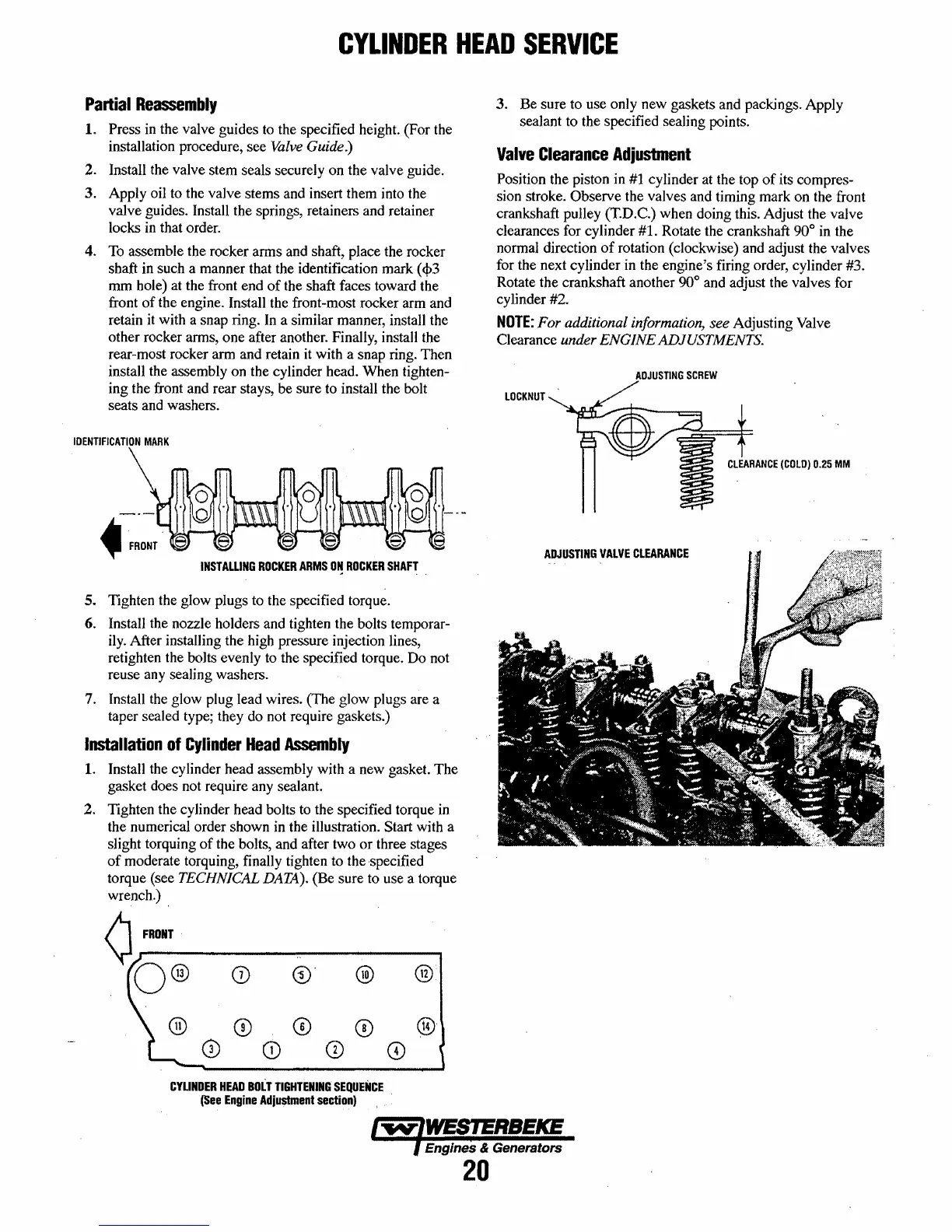
Valve
Clearance
Adjusbnent
Position the piston in
#1
cylinder at the top
of
its compres-
sion stroke. Observe the valves and timing mark on the front
crankshaft pulley
(T.D.C.) when doing this. Adjust the valve
clearances for cylinder
#1. Rotate the crankshaft 90° in the
normal direction
of
rotation (clockwise) and adjust the valves
for the next cylinder in the engine's firing order, cylinder #3.
Rotate the crankshaft another
90° and adjust the valves for
cy linder #2.
NOTE:
For additional information, see Adjusting Valve
Clearance
under ENGINE
AD]
USTMENTS.
ADJUSTING
SCREW
LOCKNUT
CLEARANCE
(COLD)
0.25
MM
ADJUSTING
VALVE
CLEARANCE
Engines & Generators
20
 Loading...


