ENGINE
ADJUSTMENTS
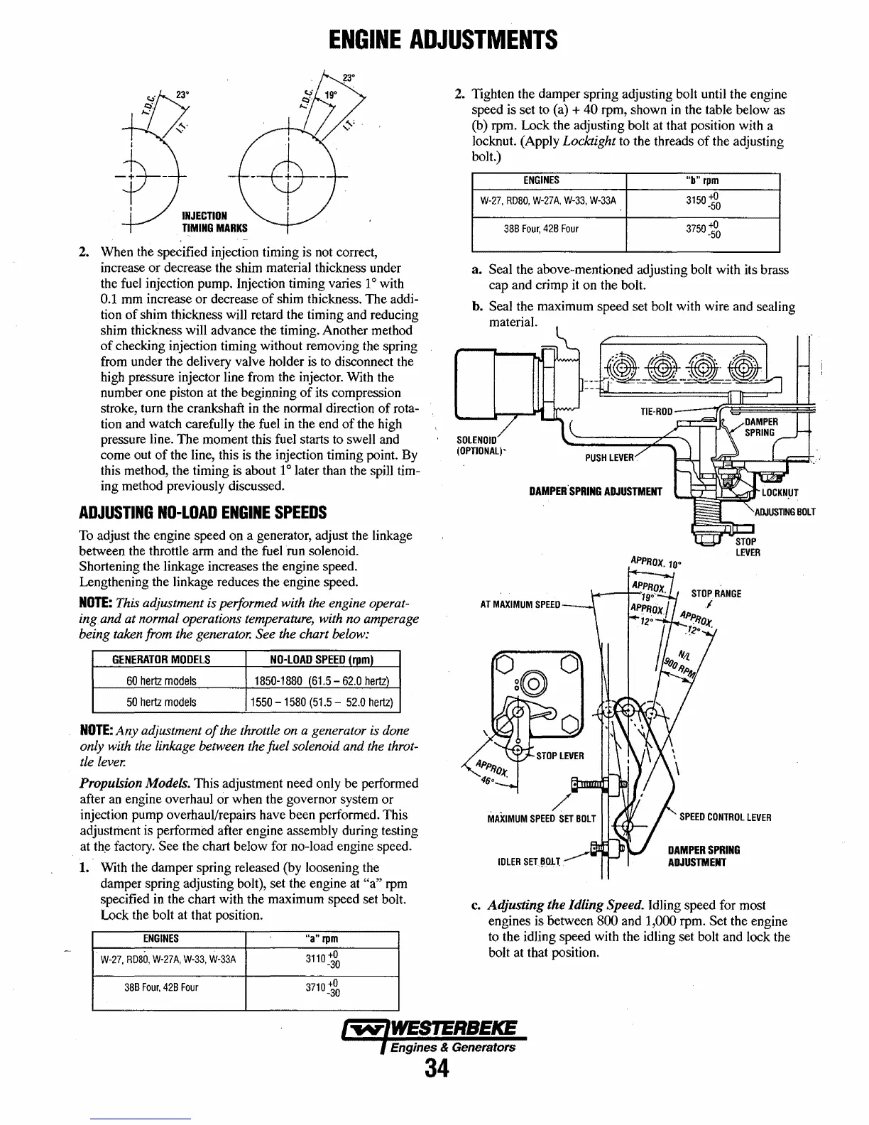
INJECTION
TIMING
MARKS
2. When the specified injection timing is not correct,
increase or decrease the shim material thickness under
the fuel injection pump. Injection timing varies
1°
with
0.1 mm increase or decrease
of
shim thickness. The addi-
tion
of
shim thickness will retard the timing and reducing
shim
thickness will advance the timing. Another method
of
checking injection timing without removing the spring
from under the delivery valve holder is
to
disconnect the
high pressure injector line from the injector. With the
number one piston at the beginning
of
its compression
stroke, tum the crankshaft
in
the normal direction
of
rota-
tion and watch carefully the fuel in the end
of
the high
pressure line. The moment this fuel starts to swell and
come out
of
the line, this
is
the injection timing point. By
this method, the timing is about 1
0
later than the spill tim-
ing method previously discussed.
ADJUSTING
NO-LOAD
ENGINE
SPEEDS
To
adjust the engine speed on a generator, adjust the linkage
between the throttle arm and the fuel run solenoid.
Shortening the linkage increases the engine speed.
Lengthening the linkage reduces the engine speed.
NOTE:
This adjustment is performed with the engine operat-
ing
and at normal operations temperature, with no amperage
being taken from the generator. See the chart below:
GENERATOR
MODElS
NO-LOAD
SPEED
(rpm)
60
hertz
models
1850-1880
(61.5
-
62.0
hertz)
50
hertz
models
1550
-1580
(51.5
52.0
hertz)
NOTE:
Any
adjustment
of
the throttle on a generator is done
only with the linkage between the fuel solenoid and the
throt-
tle
lever.
Propulsion Models. This adjustment need only be performed
after
an
engine overhaul
cir
when the governor system
or
injection pump overhaul/repairs have been performed. This
adjustment is performed after engine assembly during testing
at
th~
factory. See the chart below for no-load engine speed.
1.· With the damper spring released (by loosening the
damper spring adjusting bolt), set the engine at
"a"
rpm
specified in the chart with the maximum speed set bolt.
lock
the bolt at that position.
ENGINES
"a"
rpm
W-27,
RD80,
W·27A,
W-33,
W-33A
3110
+0
-30
38B
Four,
428
Four
3710
+0
-30
2. Tighten the damper spring adjusting bolt
unti1
the engine
speed is set to (a)
+ 40 rpm, shown
in
the table below as
(b) rpm. Lock the adjusting bolt at that position with a
locknut. (Apply Locktight to the threads
of
the adjusting
bolt.)
ENGINES
"b"
rpm
W·27,
RD80,
W-27A,
W-33,
W-33A
3150
+0
·50
38B
Four,
42B
Four
3750
+0
-50
a.
Seal the above-mentioned adjusting bolt with its brass
cap and crimp
it
on the bolt.
h.
Seal the maximum speed set bolt with wire and sealing
material.
SOLENOID
(OPTIONAL)-
DAMPER·SPRING
ADJUSTMENT
APpF/OX.1O"
STOP
LEVER
STOP
RANGE
SPEED
CONTROL
LEVER
DAMPER
SPRING
ADJUSTMENT
c.
Adjusting the Idling Speed. Idling speed for most
engines is
oetween 800 and 1,000 rpm. Set the engine
to the idling speed with the idling set bolt and lock the
bolt at that position.
Engines & Generators
34
 Loading...


