BT
GENERATOR
TROUBLESHOOTING
MAIN
STATOR
WINDINGS
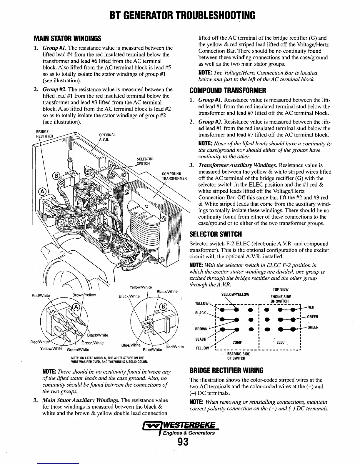
1.
Group #1. The resistance value is measured between the
lifted lead #4 from the red insulated terminal below the
transformer and lead #6 lifted from the
AC
terminal
block. Also lifted from the
AC
terminal block
is
lead #5
so as to totally isolate the stator windings
of
group
#1
(see illustration).
2.
Group #2. The resistance value is measured between the
lifted lead
#1
from the red insulated terminal below the
transformer and lead #3 lifted from the
AC
terminal
block.
Also
lifted from the
AC
terminal block
is
lead
#2
so as to totally isolate the stator windings
of
group
#2
(see illustration).
YellowlWhite
NOTE:
ON
LATER
MOOELS,
THE
WHITE
STRIPE
ON
THE
WIRE
WAS
REMOVED,
AND
THE
WIRE
IS
A
SOLID
COLOR.
NOTE:
There should
be
no continuity found between any
of
the lifted stator leads and the case ground. Also, no
contilluity should be found between the connections
of
the two groups.
3. Main Stator Auxiliary Windings. The resistance value
for these windings is measured between the black
&
white and the brown & yellow double lead connection
lifted
off
the
AC
terminal
of
the bridge rectifier (G) and
the yellow
& red striped lead lifted
off
the Voltage/Hertz
Connection Bar. There should be no continuity found
between these winding connections and the case/ground
as well as the two main stator groups.
NOTE:
The Voltage/Hertz Connection
Bar
is located
below and
just
to the left
of
the
AC
terminal block.
COMPOUND
TRANSFORMER
1.
Group #1. Resistance value is measured between the lift-
ed lead
#1
from the red insulated terminal stud below the
transformer and lead #7 lifted
off
the
AC
terminal block.
2.
Group #2. Resistance value is measured between the lift-
ed lead
#1
from the red insulated terminal stud below the
transformer and lead #7 lifted off the
AC
terminal block.
NOTE:
None
of
the lifted leads should have a continuity to
the case/ground nor should either
of
the groups have
continuity to the other.
3. Transformer Auxiliary Windings. Resistance value is
measured between the yellow
& white striped wires lifted
off
the
AC
terminal
of
the bridge rectifier (G) with the
selector switch in the ELEC position and the
#1
red &
white striped leads lifted
off
the Voltage/Hertz
Connection Bar.
Off
this same bar, lift the #2 and #3 red
& White striped leads that come from the auxiliary wind-
ings to totally isolate these windings. There should be no
continuity found from either
of
these connections to the
case/ground
or
to either
of
the two transformer groups.
SELECTOR
SWITCH
Selector switch F-2 ELEC (electronic A.V.R. and compound
transformer). This is the optional configuration
of
the exciter
circuit with the optional A.V.R. installed.
NOTE:
With
the selector switch
in
ELEC F-2 position in
which the exciter stator windings are divided,
one group is
excited through the bridge rectifier
and the other group
through the
A.
V.R.
TOP
VIEW
YELLOW/YELLOW
ENGINE
SIDE
~
OF
SWITCH
YELLOW
- - - - - - - - -
r-
- - - .. - - - - -
::.:l-
BLACK
: •
:.
•
.,
RED
~
.:.
___.-:--GREEN
r : t -
BROWN
;,.....-Y.~I
•
!.
• •
rGREEN
BLACK/.
/'.
•
•
COMP
: '
ELEC
:
YELLOW
!...
__________
!.
________ • _
~
~
BEARING
SIDE
OF
SWITCH
BRIDGE
RECTIFIER
WIRING
The
illustration shows the color-coded striped wires at the
two
AC
terminals and the color-coded wires at the
(+)
and
(-)
DC
terminals.
NOTE:
When removing or reinstalling connections, maintain
correct polarity connection on the
(+) and
(--)
DC
terminals.
Engines & Generators
93
 Loading...


