BT
GENERATOR
TROUBLESHOOTING
This troubleshooting guide will give you insights into prob-
lems which may be encountered with the WESTERBEKE
BT
brush less, transformer regulated generators. Most poten-
tial problems are covered
in
the text
of
this guide. Owing to
the simplicity
of
the equipment and controls, this trou-
bleshooting is relatively easy, once the relationship between
cause and effect is understood.
Keep in mind that a basic fundamental knowledge
of
elec-
tricity is required for this troubleshooting, and always
remember that lethal voltages are present in the circuitry;
therefore, extreme caution is essential when working on
or
troubleshooting a generator.
Only a few basic tools are necessary for diagnosis and repair.
These are hand tools:
an
amp probe and a quality volt ohm-
meter capable
of
reading less than one ohm due to the preci-
sion required
in
reading component winding resistances.
NOTE:
Do
not always rely on the vessel S instruments for
accurate readings; bring your own instruments for testing.
Before attempting any repairs, get as clear an explanation
of
the problem as possible, preferably from
an
individual wit-
nessing the problem.
In
some cases, this may bring to light a
problem which is related to the method
of
operation rather
than an equipment fault.
Bring basic repair parts with you on the initial trip to the
problem equipment, such as a regulator board when installed,
diodes and a bridge rectifier, so that if the problem should be
found in one
of
these easily replaceable parts, the problem
can be remedied early and efficiently.
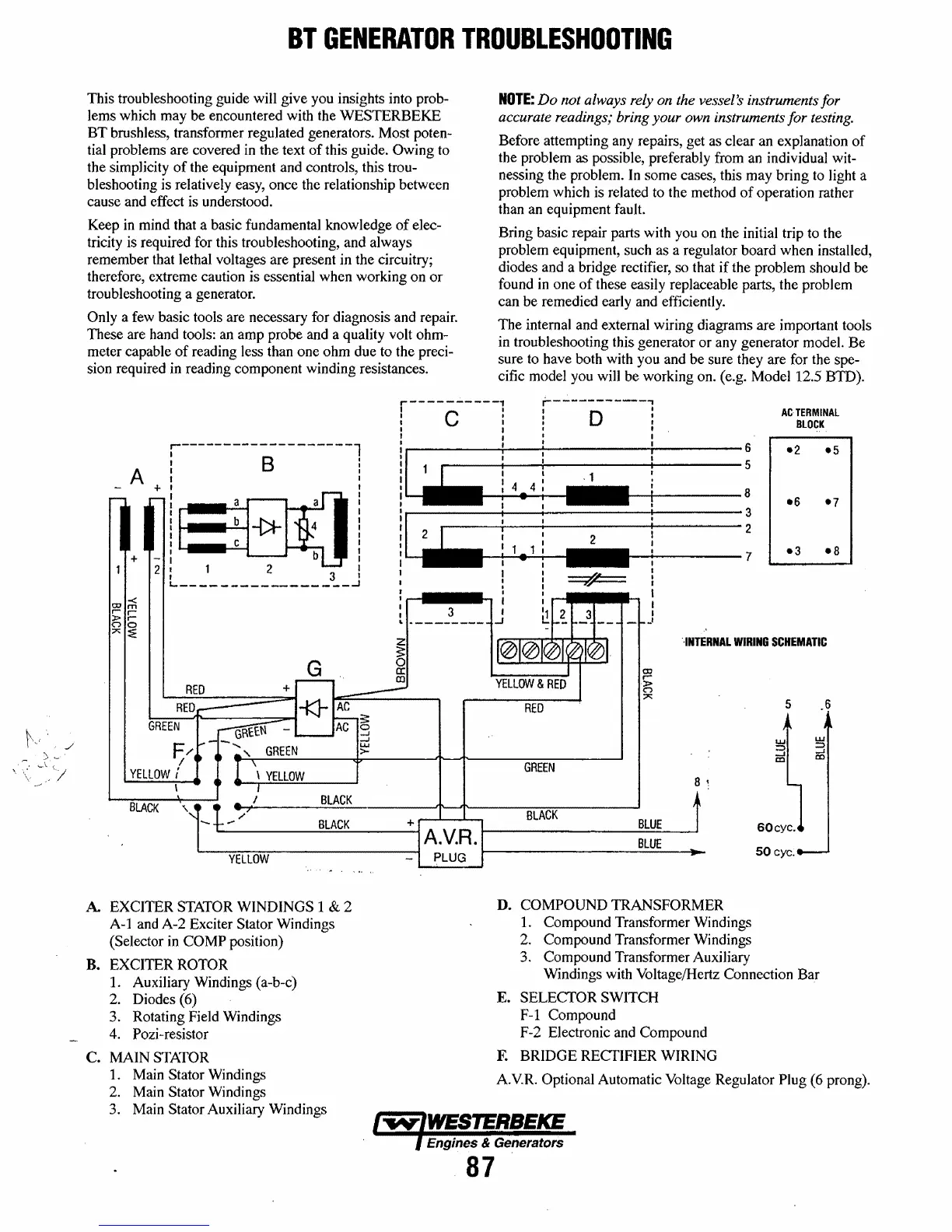
The internal and external wiring diagrams are important tools
in troubleshooting this generator or any generator modeL Be
sure to have both with you and be sure they are for the spe-
cific model you will be working on. (e.g. Model 12.5
BID).
r-------------------l
I B I
I I
A
I I
I I
+:
aoo!
II
::* 4 j
i~
:
4)
...
1--+1----:
~: ~:
1,N=
:1
1i
_2
1--
....
1---_:
, b I
I 2 I
GREEN
F/
/
YELLOW
i
BLACK
\
_____________
3
__
J
G
\
YELLOW
BLACK
LIIIIII I • I ,
I I I :
I " I
I
::
,
: I I I
t
_____
3
____
J
~
J
CD
r-
f;
;:0:::
RED
GREEN
',INTERNAL
WIRING
SCHEMATIC
5
.6
w
w
:::;)
:::;)
-'
.....J
CD
CD
8
~
,--"--"""""
BLACK
BLUE
~--------~B~L~AC~K~-----~+AVR
~--------------~~~~
• • •
BLUE
60cyc.
50cyc.
L-~Y~E~LL~O~W~--------------,
PLUG
~----------------~--~-
A EXCITER STATOR WINDINGS 1 & 2
A-1
and A-2 Exciter Stator Windings
(Selector
in
COMP position)
B. EXCITER
ROTOR
1. Auxiliary Windings (a-b-c)
2.
Diodes (6)
3. Rotating Field Windings
4. Pozi-resistor
C. MAIN
STATOR
1. Main Stator Windings
2.
Main Stator Windings
3. Main
Stator Auxiliary Windings
D.
COMPOUND TRANSFORMER
1. Compound Transformer Windings
2. Compound Transformer Windings
3. Compound Transformer Auxiliary
Windings with Voltage/Hertz Connection Bar
E.
SELECTOR SWITCH
F-1
Compound
F-2 Electronic and Compound
F.
BRIDGE RECTIFIER WIRING
A.VR. Optional Automatic Voltage Regulator Plug (6 prong).
Engines & Generators
87
 Loading...


