CYLINDER
HEAD
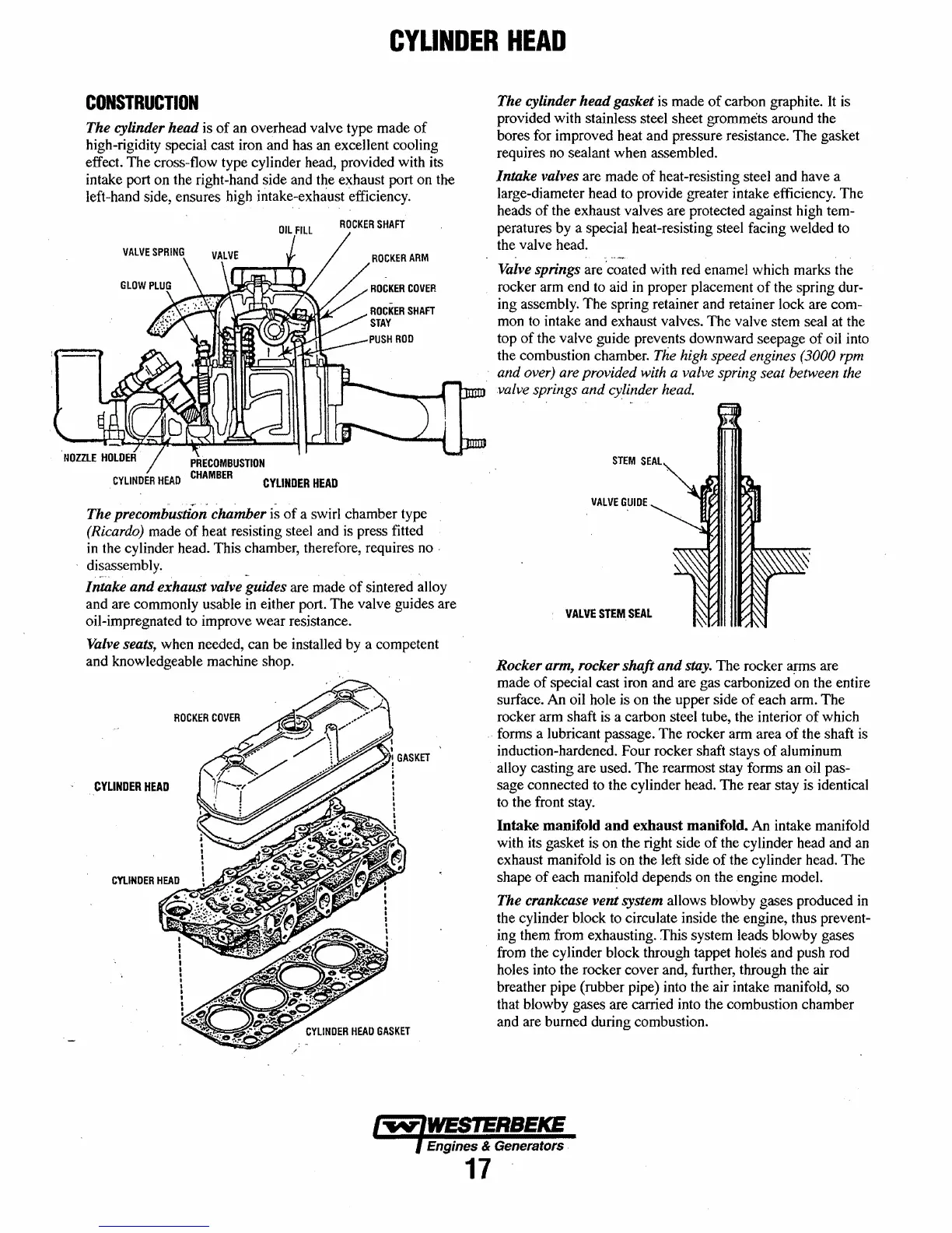
CONSTRUCTION
The
cylinder
head
is
of
an overhead valve type made
of
high-rigidity special cast iron and has an excel1ent cooling
effect.
The
cross-flow type cylinder head, provided with its
intake port on the right-hand side and
t~e
exhaust port on the
left-hand side, ensures high intake-exhaust efficiency.
ROCKER
SHAFT
CYLINDER
HEAD
The
precombustion
chamber
is
of
a swirl chamber type
(Ricardo) made
of
heat resisting steel and
is
press fitted
in the cylinder head. This chamber, therefore, requires no
'
disassembly.
Intake
and
exhaust
valve guides are made
of
sintered alloy
and are commonly usable in either port. The valve guides are
oil-impregnated to improve wear resistance.
Valve seats, when needed, can
be
installed by a competent
and knowledgeable machine shop.
ROCKER
COVER
CYLINDER
HEAD
The cylinder
head
gasket is made
of
carbon graphite. It is
provided with stainless steel sheet
grommets around the
bores for improved heat and pressure resistance. The gasket
requires no sealant when assembled.
Intake
valves are made
of
heat-resisting steel and have a
large-diameter head to provide greater intake efficiency. The
heads
of
the exhaust valves are protected against high tem-
peratures by a special heat-resisting steel facing welded to
the valve head.
Valve springs are 'coated with red enamel which marks the
rocker arm end to aid in proper placement
of
the spring dur-
ing assembly.
The
spring retainer and retainer lock are com-
mon to intake and exhaust valves. The valve stem seal at the
top
of
the valve guide prevents downward seepage
of
oil into
the combustion chamber.
The high speed engines (3000 rpm
and
over) are provided with a valve spring seat between the
valve springs
and
cylinder head.
VALVE
GUIDE
VALVE
STEM.
SEAL
Rocker
arm, rocker
shaft
and
stay.
The
rocker arms are
made
of
special cast iron and are gas carbonized on the entire
surface. An oil hole is on the upper side
of
each arm.
The
rocker arm shaft is a carbon steel tube, the interior
of
which
forms a lubricant passage. The rocker arm area
of
the shaft is
induction-hardened. Four rocker shaft stays
of
aluminum
alloy casting are used.
The
rearmost stay forms an oil pas-
sage connected to the cylinder head.
The
rear stay is identical
to the front stay.
Intake manifold and exhaust manifold. An intake manifold
with its gasket is on the right side
of
the cylinder head and an
exhaust manifold is on the left side
of
the cylinder head. The
shape
of
each
mani~old
depends on the engine model.
The crankcase
vent
system allows blowby gases produced in
the cylinder block to circulate inside the engine, thus prevent-
ing them from exhausting. This system leads blowby gases
from the cylinder block through tappet
holes and push rod
holes into the rocker cover and, further, through the air
breather pipe (rubber pipe) into the air intake manifold, so
that blowby gases are carried into the combustion chamber
and are burned during combustion.
Engines & Generators
17
 Loading...


