WMD
GENERATOR
TROUBLESHOOTING
2. Check for a short
or
open
in
the rotating armature or in
the stationary field coils.
ROTATING
ARMATURE
(RESISTANCE
VALUES)
1
1
ohm
or
less
between
slip
rings
WMD
11.0
and
12.5
KW
(1
&3)
and
(2&4)
NOTE:
4-wire units: there should
be
no
continuity found
between slip rings (1&2), (2&3) and (3&4).
If
continuity
is found, an internal short exists between these windings
and the armature should
be
replaced.
NOTE:
There should be no continuity found between any
of
the slip rings and the armature's central steel shaft.
If
continuity is found, the windings are shorted to the shaft
and the armature should be replaced.
Rotating armature slip rings are numbered from inboard
of
the generator flywheel end outward to the rear support
bearing. When referring to 2, 3 and 4-wire units, these
are the number
of
generator output leads being connected
to the load. You will find on the 11.0 and 12.5 KW units
that there are
8 leads coming from the brush rig and they
are in pairs that are combined for a total
of
4 output
leads. The number
of
wires can also
be
related to the
number
of
slip rings on the rotating armature.
REPLACEMENT
OF
FIELD
COIL(S)
1.
Field coils are connected in series and the resistance
value given
in
this text is the total
of
the four field coils.
To determine the resistance value
of
one, divide by four.
Each field coil has a mounting position on the generator
housing and cannot
be
interchanged with another field
coil.
When installing a replacement field coil(s), the installer
must ensure that the coil is correct for the mounting posi-
tion in the housing and will have the correct polarity
when excited with
9-12
volts DC.
The
field coil shoes that hold the coil securely to the gen-
erator housing are held in place by bolts that must be
properly tightened when the coil and shoe are installed to
the generator housing. When connecting the coils in
series ensure the butt connections are good and secure
and positioned away from rotating parts.
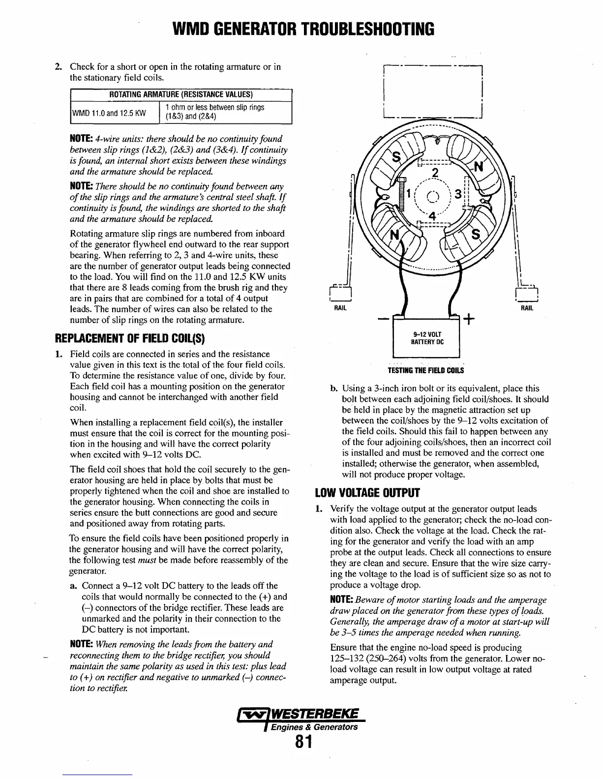
To ensure the field coils have been positioned properly in
the generator housing and will have the correct polarity,
the following test
must be made before reassembly
of
the
generator.
3.
Connect a
9-12
volt
DC
battery to the leads
off
the
coils that would normally be connected to the
(+) and
(-)
connectors
of
the bridge rectifier. These leads are
unmarked and the polarity in their connection to the
DC
battery is not important.
NOTE:
When removing the leads from the battery and
reconnecting them to the bridge rectifier, you should
maintain the same polarity as used in this test: plus lead
to
(+) on rectifier and negative to unmarked
(-)
connec-
tion to rectifier.
j
I,
II
I:~
1----1
RAil
I·----~
i j
~
__
J
9-12
VOLT
BATTERY
DC
TESTING
THE
FIELD
COILS
~
I
'\
\'
,\
~~!
"---J
RAIL
h. Using a 3-inch iron bolt
or
its equivalent, place this
bolt between each adjoining field coil/shoes.
It
should
be
held in place by the magnetic attraction set up
between the coil/shoes by the
9-12
volts excitation
of
the field coils. Should this fail to happen between any
of
the four adjoining coils/shoes, then an incorrect coil
is installed and must
be
removed and the correct one
installed; otherwise the generator, when assembled,
will not produce proper voltage.
LOW
VOLTAGE
OUTPUT
1.
Verify the voltage output at the generator output leads
with load applied to the generator; check the no-load con-
dition also. Check the voltage at the load. Check the rat-
ing for the generator and verify the load with an
amp
probe at the output leads. Check all connections to ensure
they are clean and secure. Ensure that the wire size carry-
ing the voltage to the load is
of
sufficient size
so
as not to
produce a voltage drop.
NOTE:
Beware
of
motor starting loads and the amperage
draw placed on the generator from these types
of
(oads.
Generally, the amperage draw
of
a motor at start-up will
be
3-5
times the amperage needed when running.
Ensure that the engine no-load speed is producing
125-132
(250-264)
volts from the generator. Lower no-
load voltage can result
in
low output voltage at rated
amperage output.
Engines & Generators
81
 Loading...


