FUEL
SYSTEM
DESCRIPTION
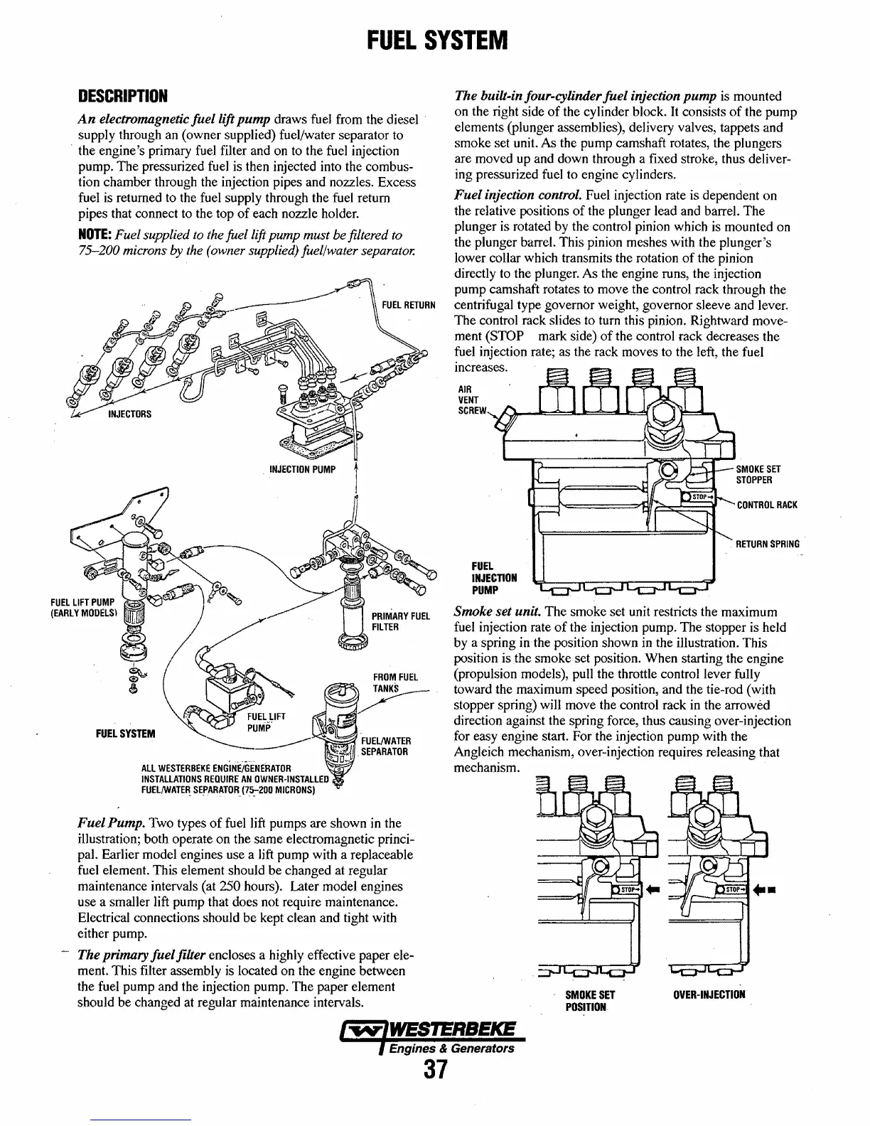
An
electrom.agnetic
fuel
lift
pump
draws fuel from the diesel .
supply through
an
(owner supplied) fuel/water separator to
. the engine's primary fuel filter and on to the fuel injection
pump. The pressurized fuel is then injected into the combus-
tion chamber through the injection pipes and nozzles. Excess
fuel is returned to the fuel supply through the fuel return
pipes that connect to the top
of
each nozzle holder.
NOTE:
Fuel supplied to the fuel lift
pump
must be filtered to
75-200 microns by the (owner supplied) fuel/water separator.
FUEL
SYSTEM
ALL
WESTERBEKE
ENG'lNEiGENERATOR
INSTALLATIONS
REQUIRE
AN
OWNER·INSTALLED
FUEL/WATER.
SE~ARATOR.
(7.5:-200
MICRONS)
FROM
FUEL
,~
FUEL/WATER
.
SEPARATOR
Fuel
Pump. Two types
of
fuel lift pumps are shown
in
the
illustration; both operate on the same electromagnetic princi-
pal. Earlier model engines use a lift pump with a replaceable
fuel element. This element should be changed at regular
maintenance intervals (at
250 hours). Later model engines
use a smaller lift pump that does not require maintenance.
Electrical connections should be kept clean and tight with
either pump.
The primary
fuel
filter encloses a highly effective paper ele-
ment. This filter assembly is located on the engine between
the fuel pump and the injection pump. The paper element
should be changed at regular maintenance intervals.
The built·in four-cylinder
fuel
injection
pump
is mounted
on the right side
of
the cylinder block.
It
consists
of
the pump
elements (plunger assemblies), delivery valves, tappets and
smoke set unit. As the pump camshaft rotates, the plungers
are moved up and down through a fixed stroke, thus deliver-
ing pressurized fuel to engine cylinders.
Fuel
injection control. Fuel injection rate is dependent on
the relative positions
of
the plunger lead and barrel. The
plunger is rotated by the control pinion which is mounted on
the plunger barrel. This pinion meshes with the plunger's
lower collar which transmits the rotation
of
the pinion
directly to the plunger. As the engine runs, the injection
pump camshaft rotates to move the control rack through the
centrifugal type governor weight, governor sleeve and lever,
The control rack slides to tum this pinion. Rightward move-
ment
(STOP mark side)
of
the control rack decreases the
fuel injection rate; as the rack moves to the left, the fuel
increases.
AIR
VENT
SCREW
.....
~~_.-.::::=:lII.oo.I=:=:::::lI
__
~
FUEL
INJECTION
PUMP
SMOKE
SET
STOPPER
CONTROL
RACK
RETURN
SPRING
Smoke set unit. The smoke set unit restricts the maximum
fuel injection rate
of
the injection pump. The stopper is held
by a spring in the position shown
in
the illustration. This
position is
the
smoke set position. When starting the engine
(propulsion models), pull the throttle control lever fully
toward the maximum speed position, and the tie-rod (with
stopper spring) will move the control rack in the arrowed
direction against the spring force, thus causing over-injection
for easy engine start. For the injection pump with the
Angleich mechanism, over-injection requires releasing that
mechanism.
SMOKE
SET
POSITION
OVER-INJECTION
Engines & Generators
37
 Loading...


