BT
GENERATOR
AC
VOLTAGE
CONNECTIONS
_11.5V
50Hz
230V50~_
120V
60Hz
1~!l~~V
.~H~
;;.
e·
fi)
((2>
il
·2
5
2
5
II
(0
@»
(I'll)
6
7
6
II
3
q;)
N
L1
N
L1
L1
N
L1
L2
N
~
AC
TERMINAL
BLOCK
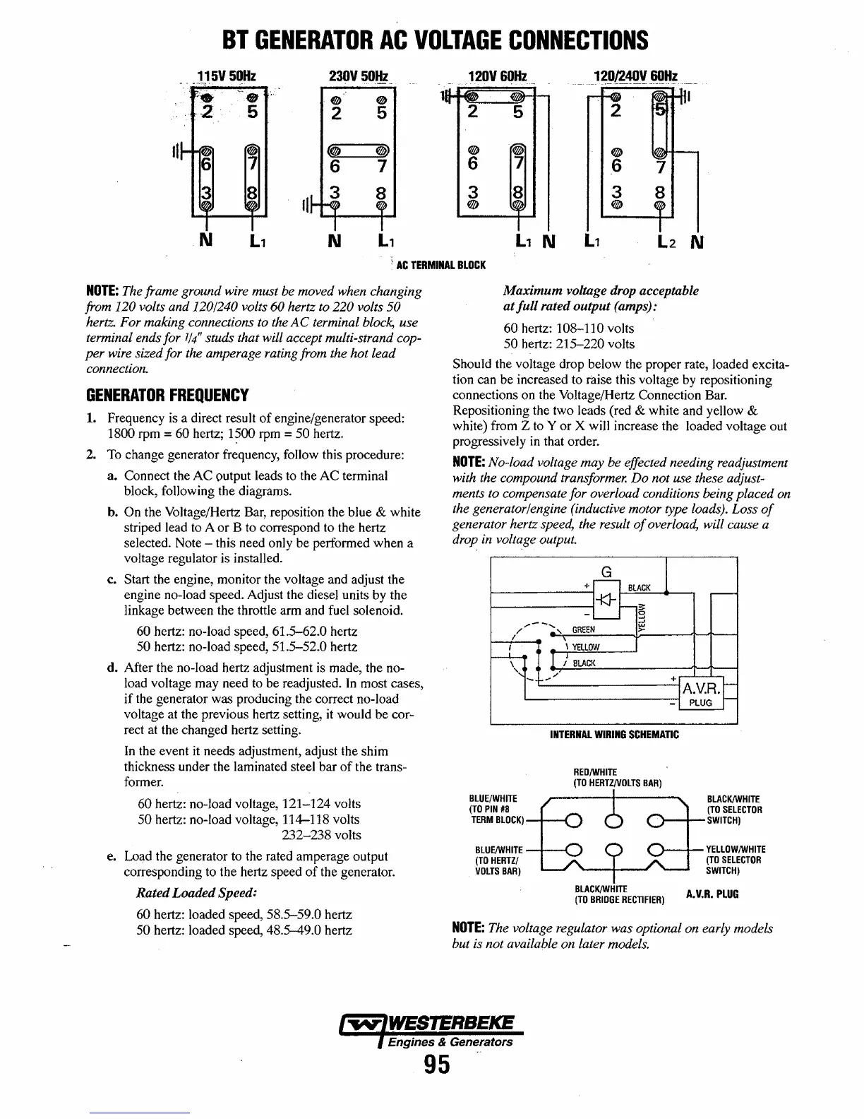
NOTE:
The frame ground wire must be moved when changing
from
120 volts and 120/240 volts
60
hertz to
220
volts 50
hertz. For making connections to the A C terminal block, use
terminal ends for
1/4"
studs that will accept multi-strand cop-
per
wire sized for the amperage rating from the hot lead
connection.
GENERATOR
FREQUENCY
1.
Frequency is a direct result
of
engine/generator speed:
1800 rpm = 60 hertz;
1?OO
rpm = 50 hertz.
2. To change generator frequency, follow this procedure:
a. Connect the
AC
output leads to the
AC
terminal
block, following the diagrams.
b.
On the VoHage/Hertz Bar, reposition the blue & white
striped lead to A or B to correspond to the hertz
selected. Note - this need only be performed when a
voltage regulator is installed.
c.
Start the engine, monitor the voltage and adjust the
engine no-load speed. Adjust the diesel units by the
linkage between the throttle arm and fuel solenoid.
60
hertz: no-load speed, 61.5-62.0 hertz
50 hertz: no-load speed, 51.5-52.0 hertz
d. After the no-load hertz adjustment is made, the no-
load voltage may need to be readjusted.
In
most cases,
if the generator was producing the correct no-load
voltage at the previous hertz setting,
it
would be cor-
rect at the changed hertz setting.
In
the event
it
needs adjustment, adjust the shim
thickness under the laminated steel bar
of
the trans-
former.
60 hertz: no-load voltage, 121-124 volts
50 hertz: no-load voltage, 114-118 volts
232-238 volts
e. Load the generator to the rated amperage output
corresponding to the hertz speed
of
the generator.
Rated
Loaded
Speed:
60 hertz: loaded speed, 58.5-59.0 hertz
50 hertz: loaded speed, 48.5-49.0 hertz
Maximum
voltage drop acceptable
at
full
rated
output
(amps):
60 hertz: 108-110 volts
50 hertz: 215-220 volts
Should the voltage drop below the proper rate, loaded excita-
tion can be increased to
raise this voltage by repositioning
connections on the Voltage/Hertz Connection Bar.
Repositioning the two leads (red & white and yellow &
white) from Z to Y or X will increase the loaded voltage out
progressively
in
that order.
NOTE:
No-load voltage may be effected needing readjustment
with the compound transformer.
Do
not use these adjust-
ments to compensate for overload conditions being placed on
the generator/engine (inductive motor type loads). Loss
of
generator hertz speed, the result
of
overload, will cause a
drop in voltage output.
G
I
+
BLACK
;----
-t::1-§
.,....--
........
GREEN
~
/
I
~
\
"-
BLUE/WHITE
(TO
PIN
#8
TERM
BLOCK)
_'\
\
YELLOW
1 )
BLACK
/'
...
+IA.v.R.~
-I
PLUG
INTERNAL
WIRING
SCHEMATIC
RED/wHITE
(TO
HERTZNOLTS
BAR)
BLACK/WHITE
(TO
SELECTOR
l---I--
SWITCH)
BLUE/WHITE
-,--,.
>---+--
YELLOW/WHITE
(TO
HERTZ/
VOLTS
BAR)
BlACK/WHITE
(TO
BRIDGE
RECTIFIER)
(TO
SELECTOR
SWITCH)
A.V.R.
PLUG
NOTE:
The voltage regulator was optional on early models
but is not available on later models.
Engines & Generators
95
 Loading...


