ALTERNATOR/REGULATOR
SERVICE
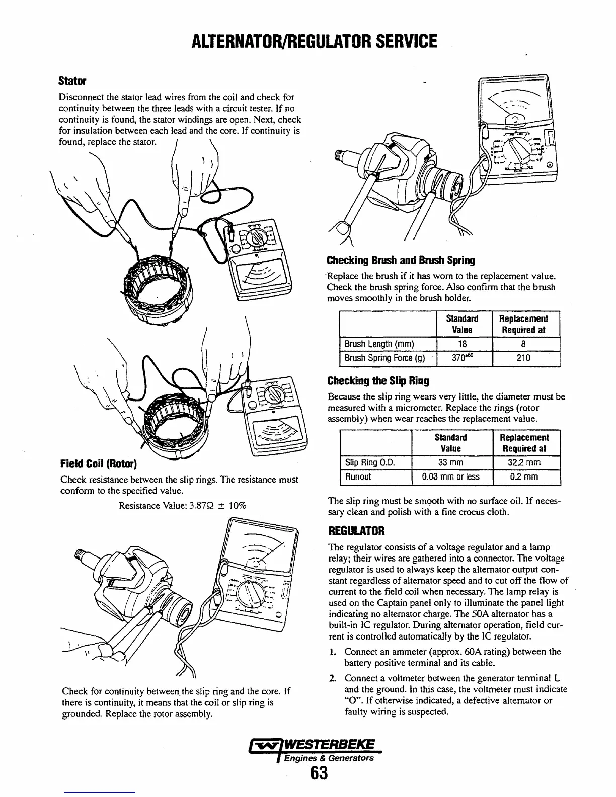
Stator
Disconnect the stator lead wires from the coil and check for
continuity between the three leads with a circuit tester.
If no
continuity is found, the stator windings are open. Next, check
for insulation between each lead and the core. If continuity
is
found, replace the stator.
Field
Coil
(Rotor)
Check resistance between the slip rings. The resistance must
confonn to the· specified value.
Resistance Value: 3.87Q
± 10%
Check for continuity between. the slip ring and the core. If
there is continuity,
it
means that the coil or slip ring
is
grounded. Replace the rotor assembly.
Checking
Brush
and
Brush
Spring
"Replace the brush if
it
has worn
to
the replacement value.
Check the brush spring force. Also confinn that the
bnIsh
moves smoothly
in
the brush holder.
Standard
Replacement
Value
Required
at
Brush
Length
(mm)
18
8
Brush
Spring
Force
(g)
3700:60
210
Checking
the
Slip
Ring
Because the slip ring wears very little, the diameter must be
measured with a micrometer. Replace the rings (rotor
assembly) when wear reaches the replacement value.
Standard
Replacement
Value
Required
at
Slip
Ring
0.0.
33mm
32.2
mm
Runout
0.03
mm
or
less
0.2mm
The slip ring must
be
sm<?Oth
with
no
surface oil.
If
neces-
sary
clean and polish with a fine crocus cloth.
REGULATOR
The regulator consists
of
a voltage regulator and a lamp
relay; their wires are gathered into a connector. The
VOltage
regulator
is
used to always keep the alternator output con-
stant regardless
of
alternator speed and to cut off the flow
of
current to the field coil when necessary. The lamp relay
is
used on the Captain panel only to illuminate the panel light
indicating no alternator charge. The
50A alternator has a
built-in
Ie
regulator. During alternator operation, field
cur~
rent
is
controlled automatically by the
Ie
regulator.
1.
Connect an ammeter (approx. 60A rating) between the
battery positive tenninal and its cable.
2. Connect a voltmeter between the generator terminal
L
and the ground.
In
this case, the voltmeter must indicate
"0".
If otherwise indicated, a defective alternator
or
faulty wiring
is
suspected.
Engines & Generators
63
 Loading...


