FUEL
SYSTEM
SERVICE
DISASSEMBLY
Fuel
Filter
Remove
the retaining nut, O-ring and filter element.
Fuel
Lift
Pump
The
fuel lift
pump
requires little
or
no maintenance. For early
model fuel lift pumps, disassemble and
change
the filter.
Later model fuel lift
pumps
require no disassembly. Fuel to
the
pump
must
be
filtered to
75-200
microns. Electrical
con-
nections must
be
clean and tight. Fuel connections at the
pump
must
be
tight and without leaks.
FUEL
LIFT
PUMP
(LATER
MODEL)
Fuel
Injection
Pump
1. Remove the fuel injection pipes.
FROM
ENGINE
PRIMARY
FUEL
FILTER
j
2. Before removing the
pump,
be
sure to
remove
the
pump
side
cover
and disconnect
the
tie-rod and
spring
from the
rack.
Then
remove the bolts fastening the injection
pump
and remove the
pump
assembly.
3.
Record the thickness and
number
of
pump
adjusting
shims to facilitate adjustment at the time
of
assembly.
4.
When
partly disassembling
the
fuel injection pump, use
the following procedure.
A
CAUTION:
00
not
attempt
to
disassemble
the
fuel
injection
pump
unless
itis
necessary.
Since
the
adjustment
of
an
injection
pump
requires
a
pump
tester
and
technical
disassembly,
reassembly
and
adjustment
of a
pump
should
not
be
performed
if
such
a
tester
and
technician
aren't
available.
Before
disassembly,
close
the
fuel
inlet
and
outlet
and
clean
the
pump's
outside
surfaces.
Keep
disassem-
bled
parts
immersed
in
clean
kerosene
and
keep
all
parts
neatly
arranged
in
order
to
avoid
confusion.
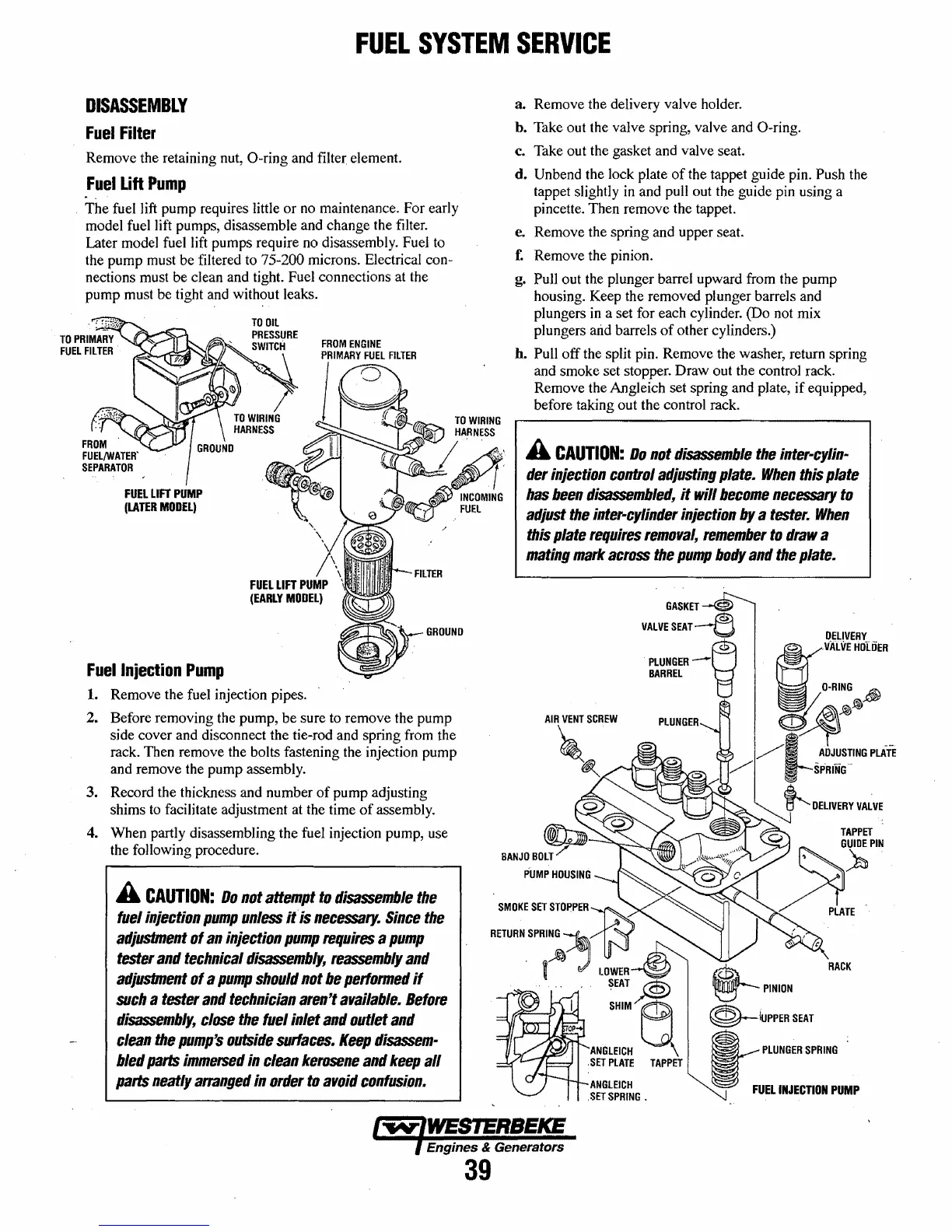
a.
Remove
the delivery valve holder.
h. Take out the valve spring, valve and O-ring.
c. Take out the gasket and valve seat.
d.
Unbend the lock plate
of
the tappet guide pin. Push the
tappet slightly in and pull out the guide pin using a
pincette.
Then
remove
the tappet.
e.
Remove
the
spring
and upper seat.
f.
Remove
the pinion.
g.
Pull out the plunger barrel upward from the
pump
housing. Keep the removed plunger barrels and
plungers in a set for each cylinder. (Do not mix
plungers
arid barrels
of
other cylinders.)
h.
Pull
off
the split pin.
Remove
the washer, return spring
and
smoke
set stopper.
Draw
out the control rack.
Remove
the AngJeich set spring and plate,
if
equipped,
before taking out the control rack.
A
CAUTION:
00
not
disassemble
the
inter-cylin"
der
injection
control
adjusting
plate.
When
this
plate
has
been
disassembled,
it
will
become
necessary
to
adjust
the
inter-cylinder
injection
by
a
tester.
When
this
plate
requires
removal,
remember
to
draw
a
mating
mark
across
the
pump
body
and
the
plate.
GASKET
i::t)
VALVE
SEAT--e
DELIVERY
ANGLEICH
,SET
SPRING
•
PLUNGER-~
BARREL
8"
0;
VALVE
HottiER
O-RING
jj)
~~~
/1/
_ADJUSTING
PLATE
"/
t-SPRfNG
~
DELIVERY
VALVE
@--PINIDN
~IUPPER
SEAT
RACK
~
PLUNGER
SPRING
FUEL
INJECTION
PUMP
Engines & Generators
39
 Loading...


