ENGINE
SHUTOFF
ENGINES
WITH
MANUAL
STOP
(Standard)
A manual stop lever is located on the outboard side
of
the
engine block just below the fuel injection pump. The damper
spring is also mounted on this same lever assembly. A throt-
tle bracket
is
provided to attach a push-pull cable. This cable
is attached
to
the shutoff lever. When pulled fully
in
the stop
direction by the cable, a lever inside the cover assembly
moves the fuel rack
of
the injection pump to the fuel stop
position, stopping the engine.
Once the engine stops, the
cable is pushed in to return the shutoff lever back into the
fuel/run position. A heavy return spring on the shutoff lever
assists in doing this. Periodically lubricate the lever and
push-pull cable to ensure free movement.
~/Id
~~?'
· i I
,~-:
,
MANUAL
STOP
.
THROTTLE
LEVER
\
OPTIONAL
KEY
SWITCH
SHUTOFF
(Models
388
and
428
only)
An optional key switch shutoff solenoid #037100 is offered
for the above two models only. This solenoid mounts in a
boss directly behind and slightly below the injection pump
mounting location, This solenoid, when energized by turning
the key-switch on, allows the injection pump fuel rack to
move to the fuel/run position allowing the engine to start to
run. When the key switch is turned off, the solenoid plunger
moves the fuel rack to the stop fuel position stopping the
engine.
Installing
and
Adjusting
the
Key
Switch
Shutoff
Solenoid
1. Remove the large plug
or
side oil filler assembly located
just behind the injection pump and slightly below it on
the engine block.
2. Visual access to the fuel injection pump fuel rack is
needed.
To
obtain this, remove the shutoff lever side
cover assembly.
3. Thread the locknut all the way onto the solenoid and
apply a small amount
of
Teflon sealant to the threads for-
ward
of
the nut.
4. Thread the solenoid into the boss on the engine block and
observe the solenoid plunger through the side cover
opening. Allow the plunger to contact the fuel rack and
move
it
fully into the shutoff position on the injection
pump. Do not thread the solenoid further into the boss so
that the plunger against the fuel rack is pushed into the
solenoid.
S.
Back the solenoid out
of
the boss 1/4 to 1/2 tum and
secure the solenoid in position with the locknut.
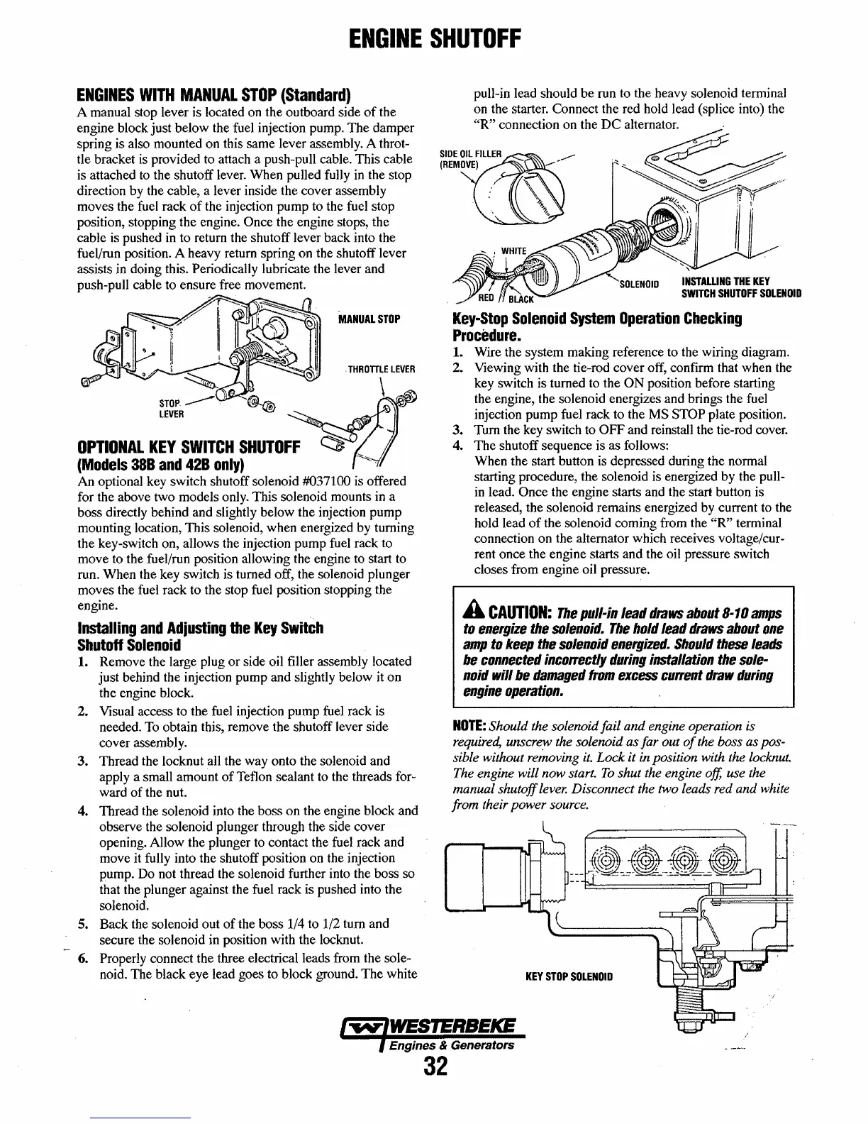
6. Properly connect the three electrical leads from the sole-
noid. The black eye lead goes to block ground.
The
white
pull-in lead should be run to the heavy solenoid terminal
on the starter. Connect the red hold lead (splice into) the
"R"
connection on the
DC
alternator.
<,~e~
~
",,~Y'>'"
, ,
~,
I "
SIDEO~l.FlllER
...........
(REMOVE)
--
:,
'\
Key-Stop
Solenoid
System
Operation
Checking
Procedure.
1. Wire the system making reference to the wiring diagram.
2. Viewing with the tie-rod cover off, confirm that when the
key switch is turned to the
ON
position before starting
the engine, the solenoid energizes and brings the fuel
injection pump fuel rack to the
MS STOP plate position.
3. Tum the key switch to
OFF and reinstall the tie-rod cover.
4.
The
shutoff sequence is as follows:
When the start button is depressed during the normal
starting procedure, the solenoid is energized by the pull-
in
lead. Once the engine starts and the start button is
released, the solenoid remains energized by current to the
hold lead
of
the solenoid coming from the
"R"
terminal
connection on the alternator which receives voltage/cur-
rent once the engine starts and the oil pressure switch
closes from engine oil pressure.
A
CAUTION:
The
pull-in
lead
draws
about
8-10
amps
to
energize
the
solenoid.
The
hold
lead
draws
about
one
amp
to
keep
the
solenoid
energized.
Should
these
leads
be
connected
incorrectly
during
installation
the
sole-
noid
will
be
damaged
from
excess
current
draw
during
engine
operation.
NOTE:
Should the solenoid fail and engine operation is
required,
unscre,w the solenoid as far out
of
the boss as pos-
sible without removing
it.
Lock
it in position with the locknut.
The engine will now start.
To
shut the engine off, use the
manual shutoff lever. Disconnect the two leads red and white
from their power source.
KEY
STOP
SOLENOID
Engines & Generators
32
 Loading...


