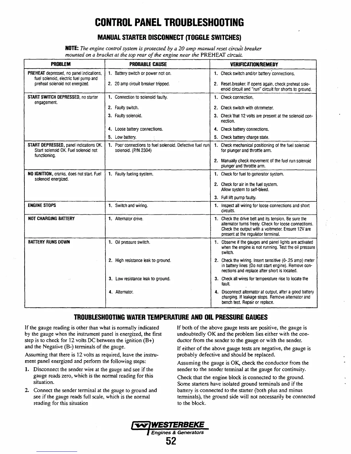
CONTROL
PANEL
TROUBLESHOOTING
MANUAL
STARTER
DISCONNECT
{TOGGLE
SWITCHES}
NOTE:
The
engine control system is protected
by
a
20
amp
manual
reset circuIt breaker
mounted
on
a bracket at the
lOp
rear
of
the engine near the PREHEAT circuit.
PROBLEM
PROBABLE
CAUSE
VERIFICAnON/REMEDY
PREHEAT
depressed,
no
panel
indications,
1.
Battery
switch
or
power
not
on.
1.
Check
switch
and/or
battery·connections.
fuel
solenoid.
electric
fuel
pump
and
preheat
solenoid
not
energized.
2.
20
amp
circuit
breaker
tripped.
2.
Reset..breaker.
If
opens
again,
check
preheat
sole-
enoid
circuit
and
"run"
circuit
for
shorts
to
ground.
START
SWITCH
DEPRESSED,
no
starter
1.
Connection
to
solenoid
faulty.
1.
Check
connection.
engagement.
2.
Faulty
switch.
2.
Check
switch
with
ohmmeter.
3.
Faulty
solenoid.
3.
Check
"that
12
volts
are
present
at
the
solenoid
con-
nection.
4.
Loose
battery
connections.
4.
Check
battery
connections.
5.
Low
battery.
5.
Check
battery
charge
state.
START
DEPRESSED,
panel
indications
OK.
1.
Poor
connections
to
fuel
solenoid.
Defective
fuel
run
1.
Check
mechanical
positioning
of
the
fuel
solenoid
Start
solenoid
OK.
Fuel
solenoid
not
solenoid.
(PIN
2304)
for
plunger
and
throttle
arm.
functioning.
2.
Manually
check
movement
of
the
fuel
run
solenoid
plunger
and
throttle
arm.
NO
IGNmON,
cranks,
does
not
start.
Fuel
1.
Faulty
fueling
system.
1.
Check
for
fuel
to
generator
system.
solenoid
energized.
2.
Check
for
air
in
the
fuel
system.
Allow
system
to
self-bleed.
3.
Fulliitt
pump
faulty.
ENGINE
STOPS
1.
Switch
and
wiring.
1.
Inspect
all
wiring
for
loose
connections
and
short
Circuits.
NOT
CHARGING
BATIERY
1.
Alternator
drive.
1.
Check
the
drive
belt
and
its
tension.
Be
sure
the
alternator
turns
freely.
Check
for
loose
connections.
Check
the
output
with
a
voltmeter.
Ensure
12V
are
present
at
the
regulator
terminal.
BATIERY
RUNS
DOWN
1.
Oil
pressure
switch.
1.
Observe
if
the
gauges
and
panel
lights
are
activated
when
the
engine
is
not
running.
Test
the
oil
pressure
switch.
2.
High
resistance
leak
to
ground.
2.
Check
the
wiring.
Insert
senSitive
(0-.25
amp)
meter
in
battery
lines
(Do
not
start
engine).
Remove
con-
nections
and
replace
after
short
is
located.
3.
Low
resistance
leak
to
ground.
3.
Check
all
wires
for
temperature
rise
to
locate
the
fault.
4.
Alternator.
4.
Disconnect
alternator
at
output,
after
a
good
battery
charging.
Jfleakage
stops.
Remove
alternator
and
bench
test.
Repair
or
replace.
TROUBLESHOOTING
WATER
TEMPERATURE
AND
OIL
PRESSURE
GAUGES
If the gauge reading is other than what
is
normally indicated
by the gauge when the instrument panel
is
energized, the first
step is to check for 12 volts DC between the ignition (B+)
and the Negative (B-) tenninals
of
the gauge.
Assuming that there
is
12 volts as required, leave the instru-
ment panel energized and perform the following steps:
1.
Disconnect the sender wire at the gauge and see if the
gauge reads zero, which
is
the normal reading for this
situation.
2. Connect the sender terminal at the gauge to ground and
see
if
the gauge reads full scale, which
is
the normal
reading for this situation
If both
of
the above gauge tests are positive, the gauge is
undoubtedly
OK
and the problem lies either with the con-
ductor from
the
sender to the gauge
or
with the sender.
If either
of
the
above gauge tests are negative, the gauge
is
probably defective and should be replaced.
Assuming the gauge is
OK, check the conductor from the
sender to the sender tenninal at the gauge for continuity.
Check that the engine block is connected to the ground.
Some starters have isolated ground terminals and
if
the
battery is connected to the starter (both plus and minus
terminals), the ground side wjJl not necessarily be connected
to the block.
Engines
& Generators
52
 Loading...


