BT
GENERATOR
TROUBLESHOOTING
Testing
the
Bridge
Rectifier
for
Faults
with
an
Ohmmeter
NOTE:
Different style/model meters may produce opposite
results from the above tests.
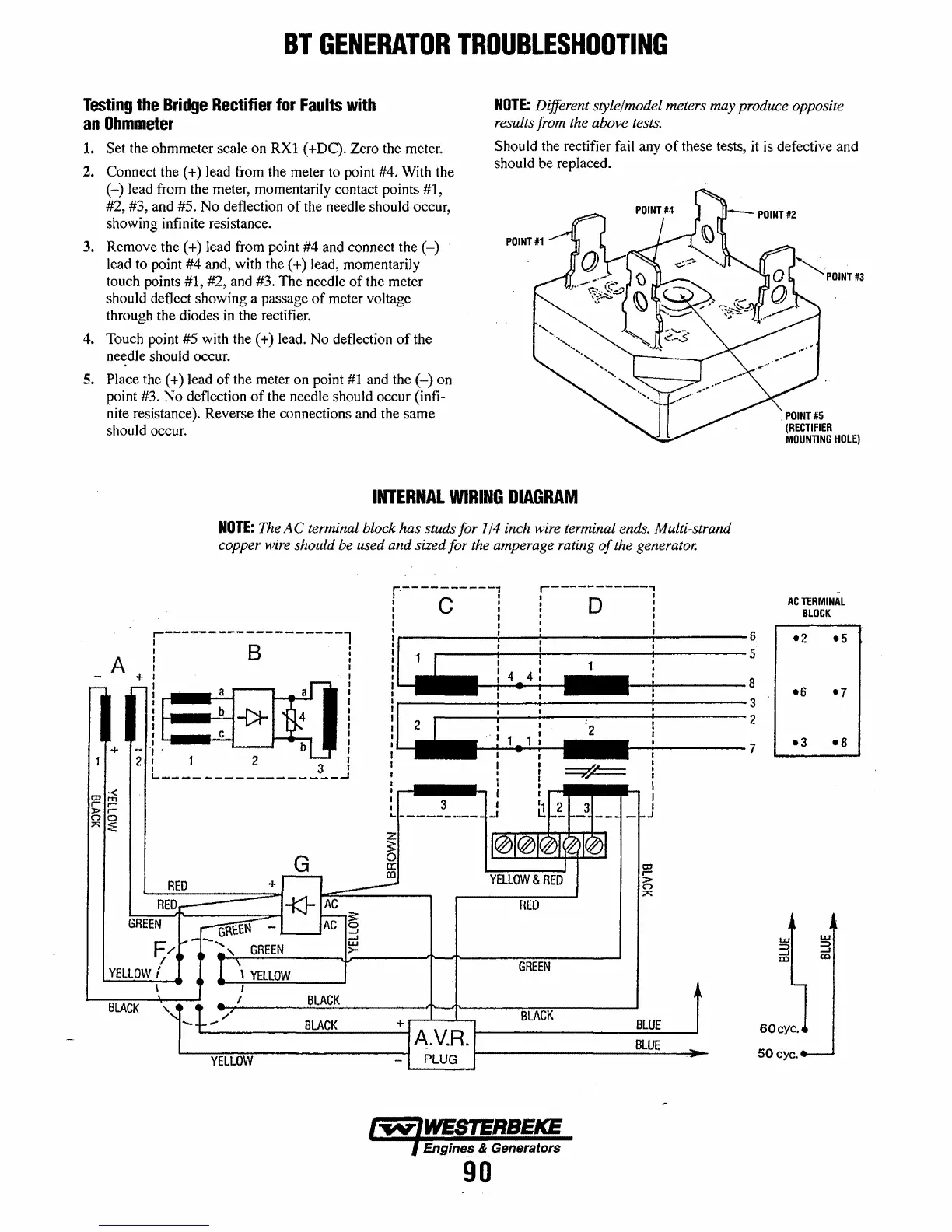
1.
Set the ohmmeter scale on RX1 (+DC). Zero the meter.
2. Connect the (+) lead from the meter to point #4. With the
(-)
lead from the meter, momentarily contact points #1,
#2, #3, and #5. No deflection
of
the needle should occur,
showing infinite resistance.
Should the rectifier fail any
of
these tests,
it
is defective and
should be replaced.
3. Remove the (+) lead from point #4 and connect the
(-)
lead to point #4 and, with the (+) lead, momentarily
touch points #1, #2, and #3. The needle
of
the meter
should deflect showing a passage
of
meter voltage
through the diodes
in
the rectifier.
4. Touch point #5 with the (+) lead.
No
deflection
of
the
needle should occur.
5. Place the (+ ) lead
of
the meter on point
#1
and the
(-)
on
point #3. No deflection
of
the needle should occur (infi-
nite resistance). Reverse the connections and the same
should occur.
INTERNAL
WIRING
DIAGRAM
NOTE:
The
AC
terminal block has studs for 1/4 inch wire terminal ends. Multi-strand
copper wire should be used
and
sized for the amperage rating
of
the generator.
r-------------------l
! B .
A + I
,...-
ro-
I
_a
a
I
I
I
I
iI~b
-()I-
4
1~
1,)
j
;
2
I
_c
I
-
b
-
+
-
I'
1
2
1 2
I I
I
I
I
I
I
===?'/===
I
I 3
I
I
I
I
~-----------------~
.
I
I
I
I
I
I
-<
I
I
I
I
CD
m
I
3
11
2
r
r
I
I
3
I
»
r
C")
0
L.
__________
-'
L:.
__
r--
---
-f-.J
I
:;><;;
~
z
101@/$10101
~
G
0
0:
I
a:I
r--
co
YELLOW
&
RED
r-
:>
RED
+
----
c.->
;;0:;:
RED~
-KJ-
AC
RED
I--
s:
GREEN
~-_AC
g
F
,...--.....
uj
,/.
•
..
'
GREEN
>-
I 1 \
GREEN
YELLOW
r
~
\
YELLOW
\ I
BLACK
BLACK
~
..
I
,~
,/
BLACK
........
BLACK
+
BLUE
A.V.R.
BLUE
...
YELLOW
-
PLUG
Engines & Generators
90
6
5
8
3
2
7
POINT
#5
(RECTIFIER
MOUNTING
HOLE)
ACTERMINAL
BLOCK
-2
-6
-3
60
eye,
50
eye.
-5
-7
-8
 Loading...


