LUBRICATION
SYSTEM
SER\(ICE
DESCRIPTION
The lubrication system uses a trochoid gear pump and a full
flow oil filter. The oil pump is driven through the
Oldham's
coupling at the rear end
of
the fuel injection pump camshaft.
Oil from the oil pump flows into the cartridge type oil filter
via the relief valve. After being filtered by this filter, oil is
delivered to various engine parts through oil galleries in the
engine block.
OIL
PUMP
DIP
STICK
__
..
_"
..........
The cartridge type oil filter,
in
which the filter body is inte-
gral with the filter element, is easy to handle.
Oil from the oil
pump is led into the filter element. When a pressure difference
between before and after the element exceeds 1 kglcm
2
due to
excessive clogging
of
the element, a bypass valve in the ele-
ment will open an oil passage bypassing the element.
As a
result, oil flows to various engine parts without filtration.
Therefore it is important to replace the oil filter regularly. The
oil filter should be replaced after the initial
50
hours
of
opera-
tion and thereafter every
100 hours
of
operation.
The trochoid gear type oil
pump
is mounted on the back
of
. the fuel injection pump on the right side
of
the cylinder block.
The oil pump houses a relief valve.
If
pump delivery oil pres-
sure exceeds 4
kglcm2,
the relief valve will open to by-pass oil
into the oil pan, thus preventing further oil pressure rise.
OIL
PUMP
ASSEN\BL
Y
OIL
PRESSURE
SWITCH
DISASSEMBLY
.......
GASKET
Oil
Filter
and
Oil
Pump
1.
Remove the oil filter.
FILTER
2. Remove the pump cover assembly, housing and gasket.
INSPECTION
Oil
Pump
1.
Outer rotor to body clearance. Using a feeler gauge,
check the clearance between the outer rotor and body. If
excessive, .replace the rotor assembly.
OUTER
ROTOR
TO
HOUSING
CLEARANCE
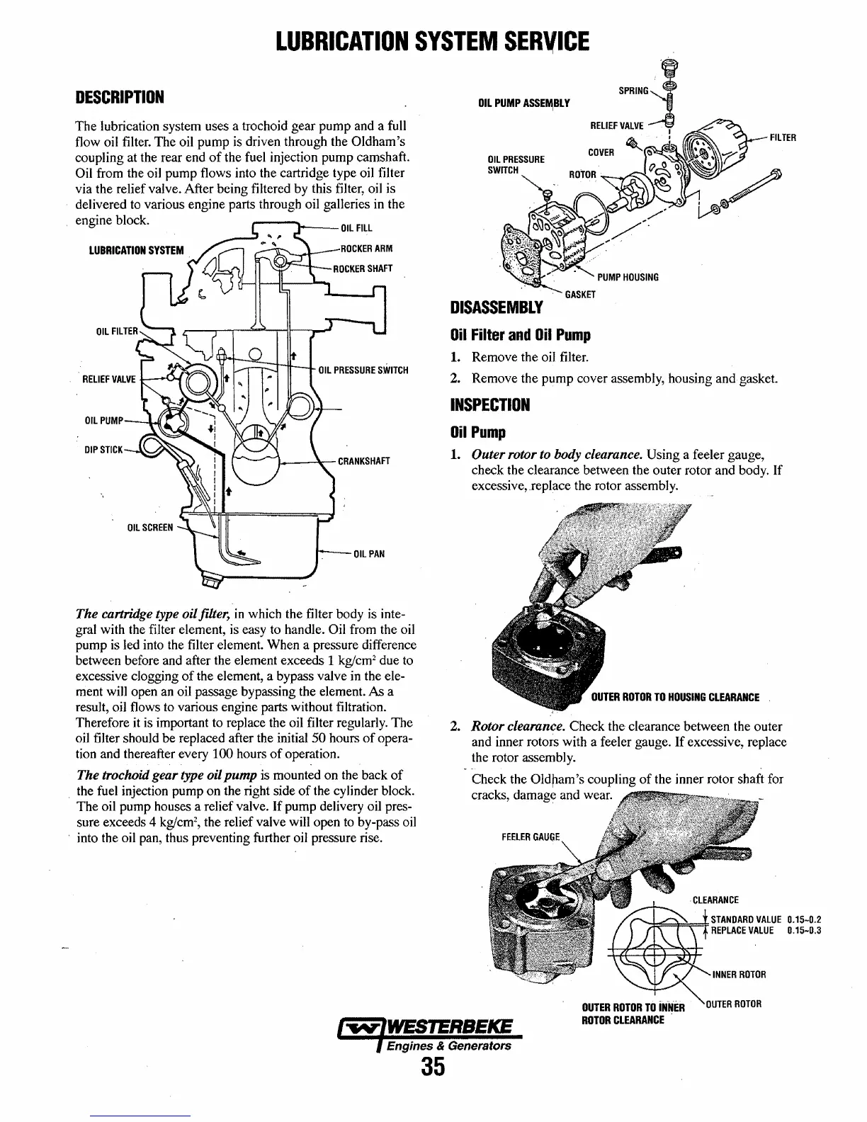
2.
Rotor clearance. Check the clearance between the outer
and inner rotors with a feeler gauge.
If
excessive, replace
the rotor assembly.
Check the
Old pam 's coupling
of
the inner rotor shaft for
cracks, damage and wear.
FEELER
GAU(lE
~'P=~=FSTANDARD
VALUE
0.15-0.2
REPLACE
VALUE
0.15-0.3
OUTER
ROTOR
TO
iNNER
ROTOR
CLEARANCE
.
Engines & Generators
35
 Loading...


