WMD
GENERATOR
TROUBLESHOOTING
NO
ELECTRICAL
OUTPUT
1.
Remove
the load from the generator and verify no output
directly at the generator output leads with a voltmeter.
2.
Check
for
proper
electrical connections. Refer to the
INTERNAL WIRING DIAGRAMS.
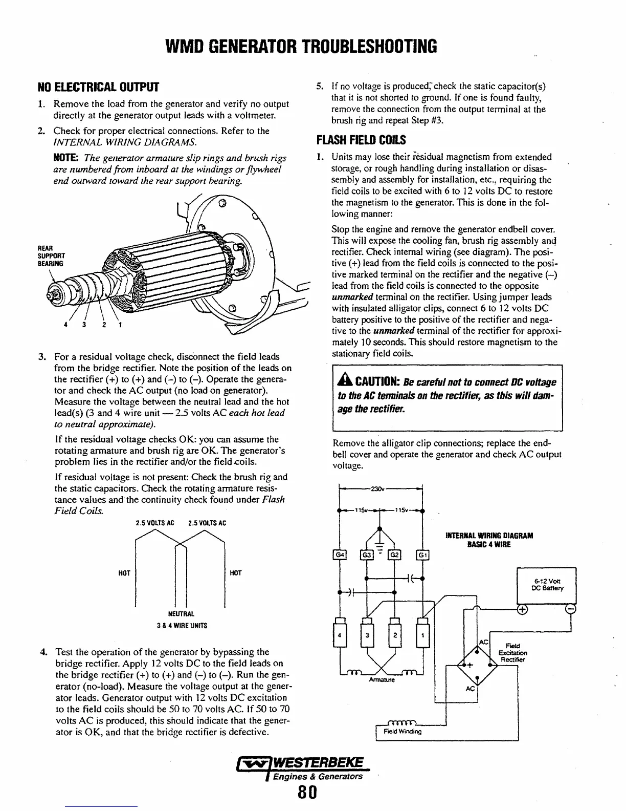
NOTE:
The generator armature slip rings and brush rigs
are numbered from illboard at the willdings
or
flywheel
end
outward toward the rear support bearing.
3.
For
a residual voltage check, disconnect the field leads
from the bridge rectifier. Note the position
of
the
leads
on
the rectifier (+) to (+) and
(-)
to
(-).
Operate the genera-
tor
and
check
the
AC
output
(no
load on generator).
Measure
the voltage between the neutral lead
and
the hot
lead(s) (3 and 4 wire unit - 2.5 volts
AC
each hot lead
to neutral approximate).
If
the
residual voltage
ch~cks
OK:
you can
assume
the
rotating
armature
and
brush rig are
OK.
The
generator's
problem
lies in the rectifier and/or the field .coils.
If residual voltage is not present: Check the brush rig and
the static capacitors. Check the rotating armature resis-
tance
values
and
the continuity check found under Flash
Field Coils.
2.5
VOLTS
AC
2.5
VOLTS
AC
HOT
HOT
NEUTRAL
3 & 4
WIRE
UNITS
4. Test the
operation
of
the generator by bypassing the
bridge
rectifier. Apply
12
volts
DC
to the field leads on
the
bridge
rectifier (+) to (+) and
(-)
to
(-).
Run the gen-
erator
(no-load). Measure the voltage output at the gener-
ator
leads.
Generator
output with
12
volts
DC
excitation
to
the field
coils
should be
50
to 70 volts
AC.
If
50
to 70
volts
AC
is produced, this should indicate that the gener-
ator
is
OK,
and
that the bridge rectifier is defective.
5. If
no
voltage is produced; check the static capacitor(s)
that
it
is
not shorted
to
ground. If one is found faulty,
remove the connection from the output tenninal at the
brush rig and repeat
Step #3.
FLASH
FIELD
COILS
1. Units may lose their residual magnetism from extended
storage,
or
rough handling during installation
or
disas-
sembly and assembly for installation, etc., requiring the
field coils
to
be excited with 6 to ] 2 volts
DC
to restore
the magnetism
to
the generator. This is done
in
the fol-
lowing manner:
Stop the engine and remove the generator endbell cover.
This will expose the cooling fan, brush rig assembly
anc~
rectifier. Check internal wiring (see diagram).
The
posi-
tive (+) lead from the field coils is connected to the posi-
tive marked terminal on the rectifier and the negative
(-)
lead from the field coils is connected to the opposite
unmarked terminal on the rectifier. Using
jumper
leads
with insulated alligator clips, connect 6 to
12
volts
DC
battery positive to the positive
of
the rectitier and nega-
tive to the
unmarked terminal
of
the rectifier for approxi-
mately ]
0 seconds. This should restore magnetism to the
stationary field coils.
A
CAUTION:
Be
careful
not
to
connect
DC
voltage
to
the
AC
terminals
on
the
reclifiet;
as
Ihis will
dam-
age
the
rectifier.
Remove the alligator clip connections; replace the end-
bell cover and operate the generator and check
AC
output
voltage.
t----23Qv----...I
Armature
INTERNAL
WIRING
DIAGRAM
BASIC
4
WIRE
AC
6-12
vott
OCBanery
Engines & .Generators
80
 Loading...


