CYLINDER
HEAD
SERVICE
DISASSEMBLY
1. Remove the air breather pipe. Remove the water bypass
hose if provided.
2. Remove the fuel injection lines.
3. Remove both the intake manifold and exhaust manifold
assemblies.
4. Remove the rocker cover.
S.
Remove the rocker arms and rocker shaft as an assembly.
6. Remove the push rods.
7. Remove the cylinder head assembly by loosening the
head bolts in the numerical order shown below.
®
®
®
®
®
CYLINDER
HEAD
BOLTS
LOOSENING
SEQUENCE
8. Remove the cylinder head gasket.
9.
Partly disassemble the cylinder head assembly as fol-
lows:
a.
Remove the thermostat housing. Remove the thermo-
stat and thermostat gasket.
b. Remove the fuel injectors and sealing washers.
c.
Remove the glow plug lead wires and remove the
glow plugs.
d. Using a valve spring com presser, compress the
spring for each valve. Remove the retainer lock
and then remove the retainer, spring and valve.
Place
the removed valves and other parts
in
order
by
each
cylinder.
e.
A valve spring seat
of
2mm thick for each spring is fit-
ted
on
the cylinder head surface. Be careful not to lose
the spring seats.
INSPECTION
Cylinder
Head
NOTE:
See SERVICE STANDARDS for tolerances and mea-
surements. .
1. Before cleaning the cylinder head, check it for cracks,
damage and water leaks.
2. Hot tank the cylinder head to thoroughly clean all sur-
faces and oil passages.
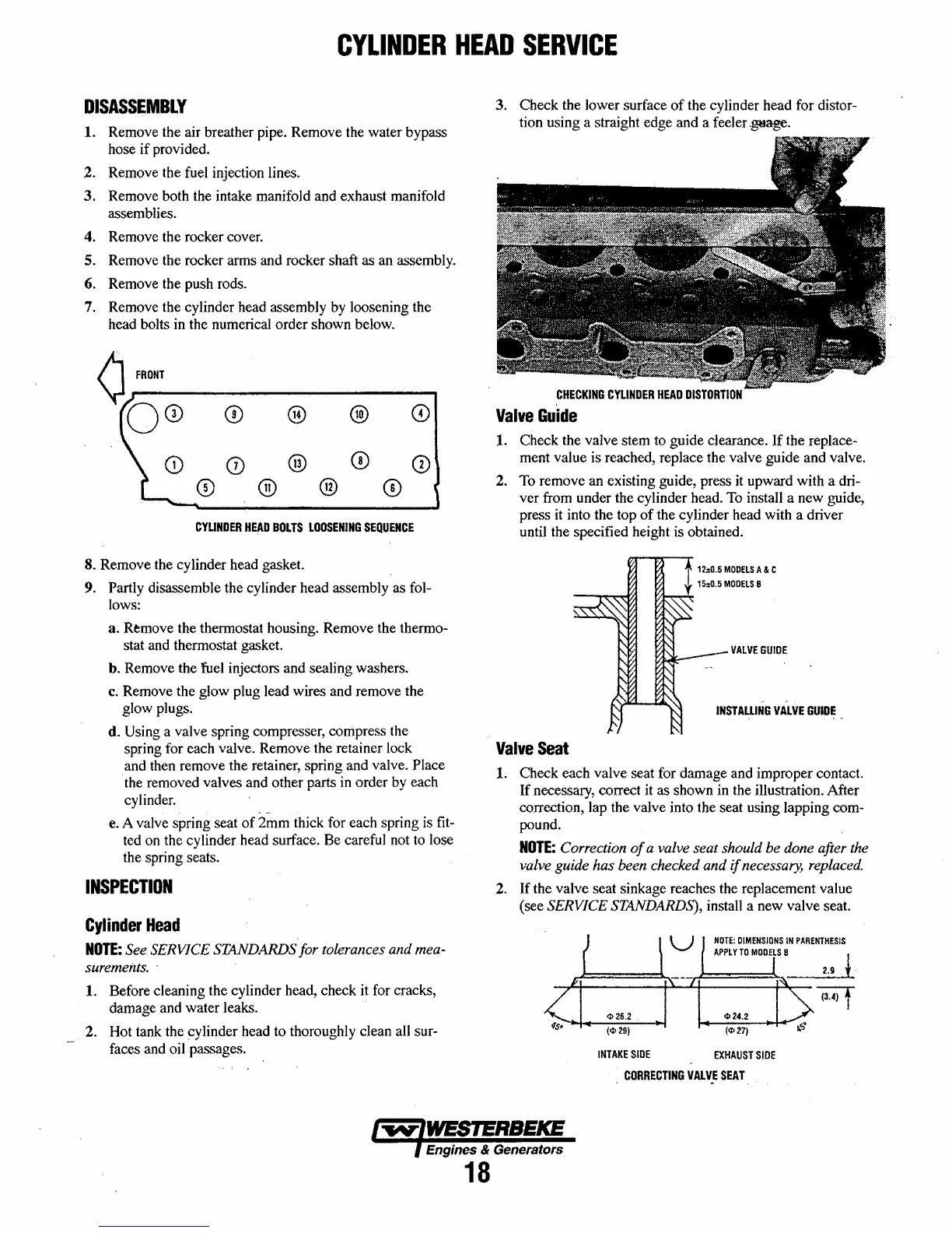
3. Check the lower surface
of
the cylinder head for distor-
tion using a straight edge and a feeler
~.
CHECKING
CYLINDER
HEAD
DISTORTION
Valve
Guide
1.
Check the valve stem to guide clearance.
If
the replace-
ment value is reached, replace the valve guide and valve.
2. To remove an existing guide, press
it
upward with a dri-
ver from under the cylinder head.
To
install a new guide,
press
it
into the top
of
the cylinder head with a driver
until the specified height is obtained.
12:0.5
MODELS
A & C
VALVE
GUIDE
INSTALLING
VALVE
GUIDE
Valve
Seat
1. Check each valve seat for damage and improper contact.
If necessary, correct
it
as shown
in
the illustration. After
correction, lap the valve into the seat using lapping com-
pound.
NOTE:
Correction
of
a valve seat should
be
done after the
valve guide has been checked and
if
necessary, replaced.
2. If the valve seat sinkage reaches the replacement value
(see
SERVICE STANDARDS), install a new valve seat.
2.9
t
INTAKE
SIDE
EXHAUST
SIDE
CORRECTING
VALVE
SEAT
. -
Engines
&
Generators
18
 Loading...


