DC
ELECTRICAL
SYSTEM
DESCRIPTION
The
DC
Circuit functions to start, operate and stop the
gener~
ator's engine. The circuit
is
best understood
by
reviewing the
DC
ELECTRICAL
SYSTEM
WIRING
DIAGRAMS.
The
engine's
DC wiring
is
designed with three simple basic
circuits:
preheat, slart, and
run
or stop.
Engine
12-Volt
Control
Circuit
The engine has a ] 2 volt DC electrical control circuit that
is
shown in the wiring diagrams. Refer
to
these diagrams when
troubleshooting or when servicing the DC electrical system
on the engine.
A
CAUTION:
To
avoid
damage
to
the
battery
charg-
ing
circuit,
never
shut
0"
the
engine
battery
switch
while
the
engine
is
running.
Shut
off
the
engine
battery
switch,
however,
to
avoid
electrical
shorts
when
working
on
the
engine's
electrical
circuit.
CHARGING
SYSTEM
The charging system consists
of
an alternator, a voltage
regulator, an engine DC wiring harness,
an
engjne~mounted
DC
circuit breaker, a battery and connecting wires. Because
of
the use
of
integrated circuits (IC's) the electronic voltage
regulator is very compact and
is
mounted internally
or
on the
back
of
the alternator.
ALTERNATOR
TROUBLESHOOnNG
If you suspect that
the
alternator
is
not
producing enough
voltage
to
charge the engine's battery, check the following:
A
WARNING:
A
failed
aftemator
can
become
very
hot.
Do
not
touch
until
the
alternator
has
cooled
down.
o
Make
certain your alternator
is
securely mounted.
o Check the drive belts for proper tension.,
o Inspect for loose
or
disconnected wires at the alternator.
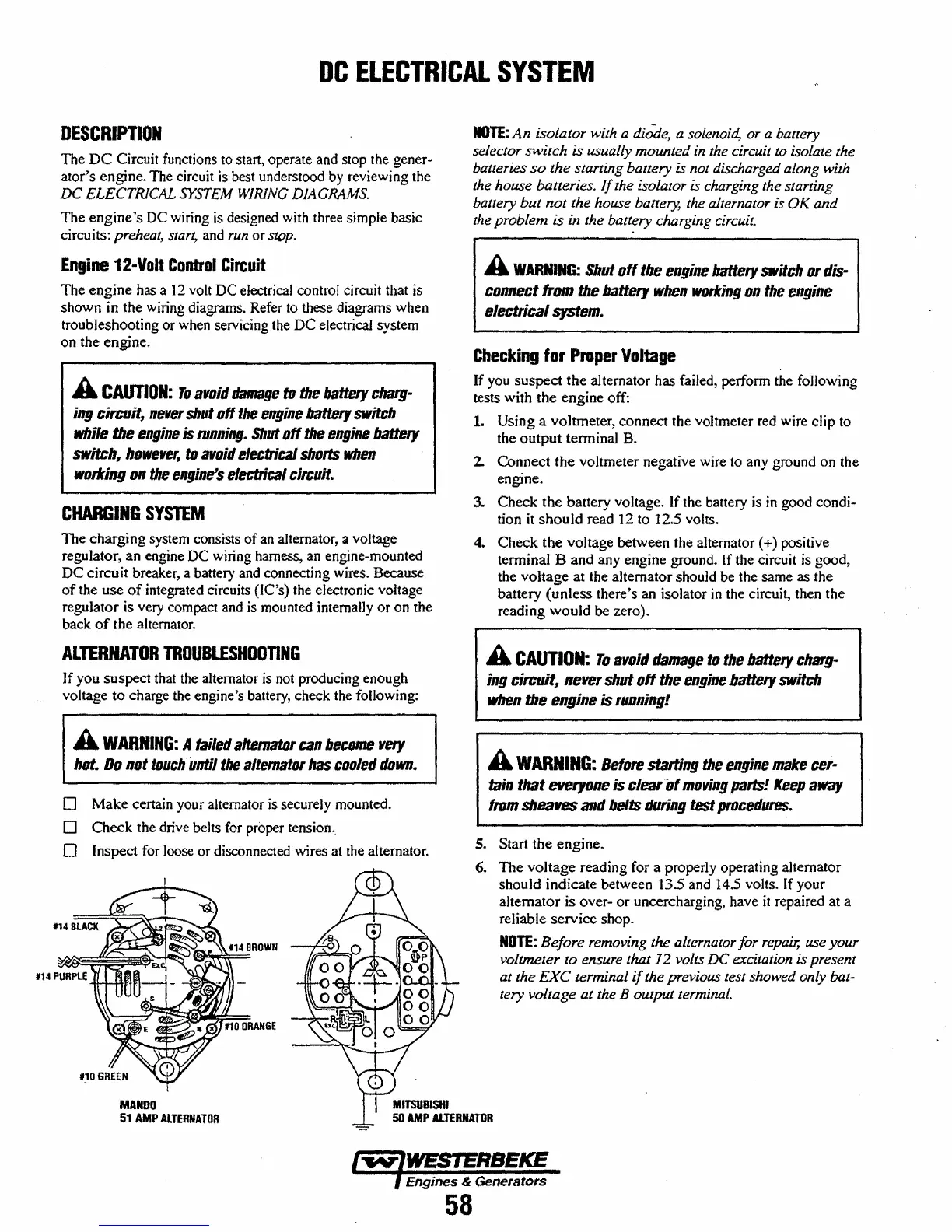
MANDO
51
AMP
AlTERNATOR
NOTE:
An
isolator with a diode, a solenoid, or a ballery
selector switch
is usually mounted
in
the circuit to isolate the
balleries
so
the
starling battery is not discharged along with
the house batteries.
If
the isolator is charging the starting
battery
but
not
the house battery, the alternator is
OK
and
the problem
is in lhe battery charging circuit.
A
WARNING:
Shut
off
the
engine
battery
switch
or
dis-
connect
from
the
battery
when
working
on
the
engine
electrical
system.
Checking
for
Proper
Voltage
If you suspect
the
alternator has failed, perform the folJowing
tests with the engine off:
1. Using a voltmeter, connect the
voltmeter red wire clip to
the
output
terminal B.
2. Connect
the
voltmeter negative wire to any ground on the
engine.
3. Check the battery voltage. If the battery is
in
good
condi~
tion
it
should
read
]2
to 12.5 volts.
4.
Check the voltage between the alternator (+) positive
terminal B and any engine ground. If the circuit
is
good,
the voltage at the alternator should be the same as the
battery (unless there's an isolator
in
the circuit, then the
reading
would
be zero).
A
CAUTION:
To
avoid
damage
to
the
battery
chalg
..
ing
citeuit,
never
shut
off
the
engine
battery
switch
when
the
engine
is
running!
A
WARNING:
Before
stalfing
the
engine
make
cel-
fain
that
everyone
is clealof
moving
parts!
Keep
away
from
sheaves
and
belts
during
test
procedures.
5. Start the engine.
6. The voltage reading for a properly operating alternator
should indicate between
13.5 and
14.5
volts. If your
alternator is over-
or
uncercharging, have
it
repaired at a
reliable service shop.
NOTE:
Before
removing the alternator for
repair,
use
your
voltmeter to ensure
that]
2 volts
DC
excitation is present
at the
EXC
lerminal
if
the previous test showed only bat-
tery vollage at the B oUlput terminal.
Engines & Generators
58
 Loading...


