BT
GENERATOR
TROUBLESHOOTING
NO-LOAD
VOLTAGE
ADJUSTMENT
Voltage adjustment is made with the generator regulation
being governed by the
compound
transformer.
1.
The
selector switch must
be
in the
CaMP
position.
2. Operate the generator, apply a moderate load momentari-
ly and remove it. Note the voltage
output
from the gener-
ator's
120 volt leg(s) (220 volt
50
hertz).
The
no-load
voltage should
be
between 121--124 volts at
61.5-62
hertz
(222-226
volts at 51.5
-52
hertz).
NOTE:
The no-load voltage should be adjusted to the volt-
age produced by the generator once started, and a
momentary load should be applied to excite the trans-
former, and then removed. The voltage produced
by
the
generator after this momentary load is removed is no-
load voltage.
3.
To raise
or
lower the voltage, shims
of
varying thickness
(non-conductive material) are placed
or
removed from
under the steel laminated bar on top
of
the
compound
transformer.
The
material used for
shimming
should not
soften' at temperatures in the
176°P (80°C) range. A small
reduction in no-load voltage
(1
at 3 volts) can sometimes
be
accomplished
by
gently tapping the top
of
the laminat-
ed
steel
bar
to reduce the
gap
between
the
existing
shims
and the transformer core.
Varying shim thickness
by
.001 inch (0.025
mm)
will change
the no-load voltage by
4-6 volts. (Adding shim thickness will
raise voltage; lessening shim thickness will lower voltage.) .
VOLTAGE/HERll
CONNECTION
BAR
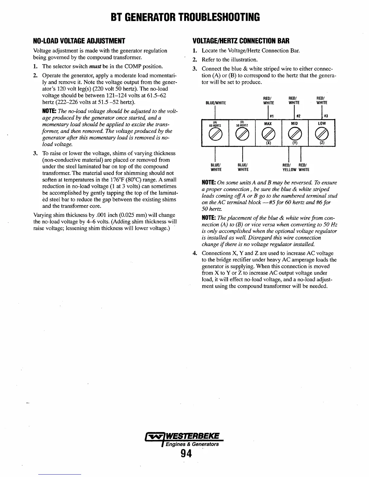
1. Locate the Voltage/Hertz Connection Bar.
2. Refer to the illustration.
3.
Connect the blue & white striped
wire
to either connec-
tion (A)
or
(B) to correspond to the hertz that
the
genera-
tor will
be
set to produce.
BLUEjWHITE
RED/
WHITE
RED!
WHITE
RED!
WHITE
#3
(8)
MAX
MID
LOW
00000
BlUEI
WHITE
BLUE{
WHITE
(Xl
(Y)
(Zl
RED/
REOI
YEllOW
WHITE
NOTE:
On some units A and B may be reversed.
To
ensure
a proper connection, be sure the blue
& white striped
leads coming
off
A or B go to the numbered terminal stud
on the
AC
terminal block
-#5
for
60
hertz and #6 for
50
hertz.
NOTE:
The placement
of
the blue & white wire from con-
nection
(A)
to
(B)
or
vice versa when converting to 50 Hz
is only accomplished when the optional voltage regulator
is installed as well. Disregard this wire connection
change
if
there is no voltage regulator installed.
4. Connections X, Y and Z are used to increase
AC
voltage
to the bridge rectifier under heavy
AC
amperage loads the
generator is supplying. When this connection is moved
from X to Y
or
Z to increase
AC
output voltage under
load,
it
will effect no-load voltage, and a no-load adjust-
ment using the compound transformer will
be
needed.
Engines & Generators
94-
 Loading...


