CYLINDER
BLOCK
SERVICE
DISASSEMBLY
1. For removal
of
a the cylinder head and related parts, refer
to
DISASSEMBLY under CYLINDER HEAD SERVICE.
2. For removal
of
the water pump and electrical equipment,
refer to their respective sections.
3. Pull off the push rods, then pull out the tappets upward.
4. Remove the fuel filter.
5. Loosen the crankshaft pulley nut, then take off the pulley
and washer.
6. Loosen the flywheel mounting bolts and remove the fly-
wheel.
7.
Remove the back plate and rear oil seal case.
8. Remove the lube oil pump gear bearing housing. Remove
the gear case, but first
it
is
necessary to remove the tie-
rod located
at
the right front (beside the injection pump)
of
the cylinder block and to remove the stopper spring
and tie-rod from the injection pump's fuel rack.
A
CAUTION:
Be
sure
tD
separate
the
injection
pump
rack
from
the
tie-rod
before
removing
the
gear
case.
The
front
plate
is
bolted
to
the
cylinder
block
frDm
inside
the
gear
case;
therefore,
be
care-
ful
nDt
tD
drive
Dut
the
gear
case
tDgether
with
the
front
plate.
Also,
be
careful
not
to
damage
the
dowel
pins.
9. Remove the fuel injection pump.
10. Remove the governor weight bolts. Remove the weights.
11. Remove the pump camshaft bolt.
12. Remove the oil filter and the oil pump assembly. Then
pull out the injection pump camshaft.
13. Remove the gears. Then remove the front plate.
14. Remove the camshaft.
15. Turn the engine upside down. Remove the oil pan and oil
screen.
16. Remove the nuts from the big end
of
each connecting rod
and remove the cap. Push the piston and connecting rod
assembly upward out
of
the cylinder block. Keep
Hie
removed parts in order for each cylinder. When pushing
out the piston and connecting rod assembly, put a
wooden block against the cap mating surface
of
the rod
so as not to damage the metal surface.
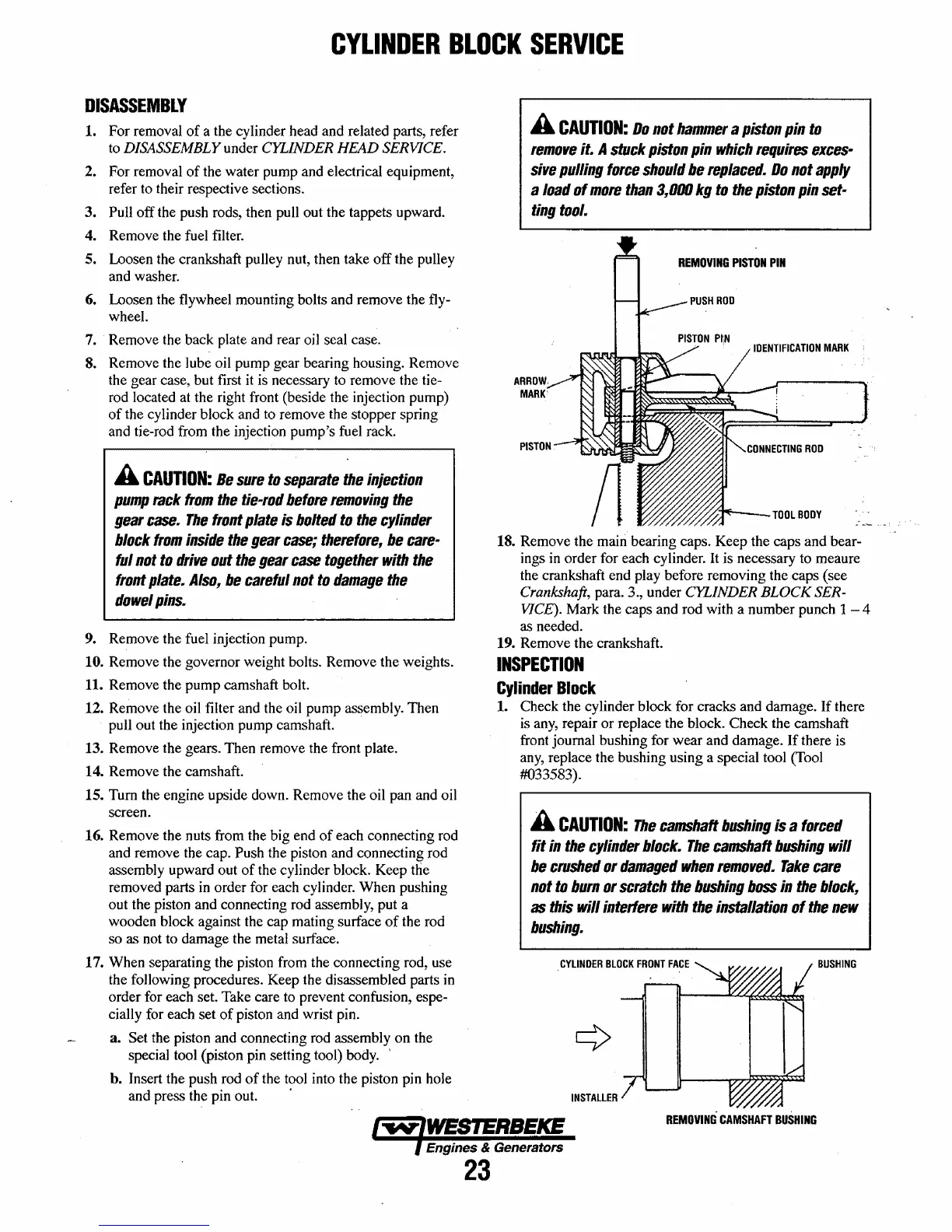
17. When separating the piston from the connecting rod, use
the following procedures. Keep the disassembled parts
in
order for each set. Take care to prevent confusion, espe-
cially for each set
of
piston and wrist pin.
a. Set the piston and connecting rod assembly on the
special tool (piston pin setting tool) body. '
h. Insert the push rod
of
the tool into the piston pin hole
and press the pin out. .
A
CAUTION:
Do
not
hammer
a
piston
pin
tD
remDve
it. A
stuck
piston
pin
which
requires
exces-
sive
pulling
force
should
be
replaced.
Do
not
apply
a
IDad
of
mDre
than
3,000
kg
tD
the
pistDn
pin
set-
ting
tool.
REMOVING
PISTON
PIN
IDENTIFICATION
MARK
"///'//./~~---TOOL
BODY
18. Remove the main bearing caps. Keep the caps and bear-
ings
in
order for each cylinder. It is necessary to meaure
the crankshaft end play before removing the caps (see
Crankshaft, para. 3., under CYLINDER
BLOCK
SER-
VICE). Mark the caps and rod with a number punch 1 4
as needed.
19. Remove the crankshaft.
INSPECTION
Cylinder
Block
1. Check the cylinder block for cracks and damage. If there
is
any, repair or replace the block. Check the camshaft
front journal bushing for wear and damage.
If
there is
any,
replace the bushing using a special tool (Tool
#033583).
A
CAUTION:
The
camshaff
bushing
is a
fDrced
fit
in
the
cylinder
block.
The
camshaff
bushing
will
be
crushed
or
damaged
when
removed.
Take
care
not
to
burn
or
scratch
the
bushing
boss
in
the
block,
as
this
will
interfere
with
the
installation
of
the
new
bushing.
BUSHING
REMOVING
CAMSHAFT
BUSHING
Engines & Generators
23
 Loading...


