RAW
WATER
PUMP
SERVICE
RAW
WATER
PUMP
-
PN
33636
PUMP
OVERHAUL
Disassembly
The pump, as removed from the engine, will have hose
attachment nipples threaded into its inlet and outlet ports.
They may be
left
in
place or removed if they interfere with
the pump disassembly. Note the port location and positioning
if
removed.
1. Remove the six cover plate screws, cover plate, and the
cover plate gasket.
NOTE:
Replacement
of
the cover plate gasket is recom-
mended; however,
if
you are going to reuse
it,
keep the
gasket submerged in water until the
pump
is reassembled.
If
it's allowed to
dry,
the gasket will shrink and not be
reusable.
2. Remove the impeller with its drive screw from the pump
housing.
3. Remove the screw and sealing washer and remove the
cam from the pump housing.
4. Remove the retaining ring.
5. Support the pump housing, at the mounting flange end,
on an arbor press, and with a drift, press out the shaft and
bearings from the pump housing.
6. With the pump housing supported, push the seals out
of
the pump housing. Push the impeller side seal out the
impeller side, then lift the spacer out. Then push the
bearing side seal out the bearing side.
7. Supporting the bearing's inner race, push the shaft out
of
the bearings.
Inspection
Inspect all parts and replace those showing wear or corro-
sion.
Reassembly
1. Install the seals and spacer in the pump housing. Push the
impeller side seal into the housing. Rotate the pump and
install the spacer against the seal face.
Push the bearing
side seal into the housing from the bearing side.
NOTE:
The seals' flat surfaces that have printing and
numbers face toward each other.
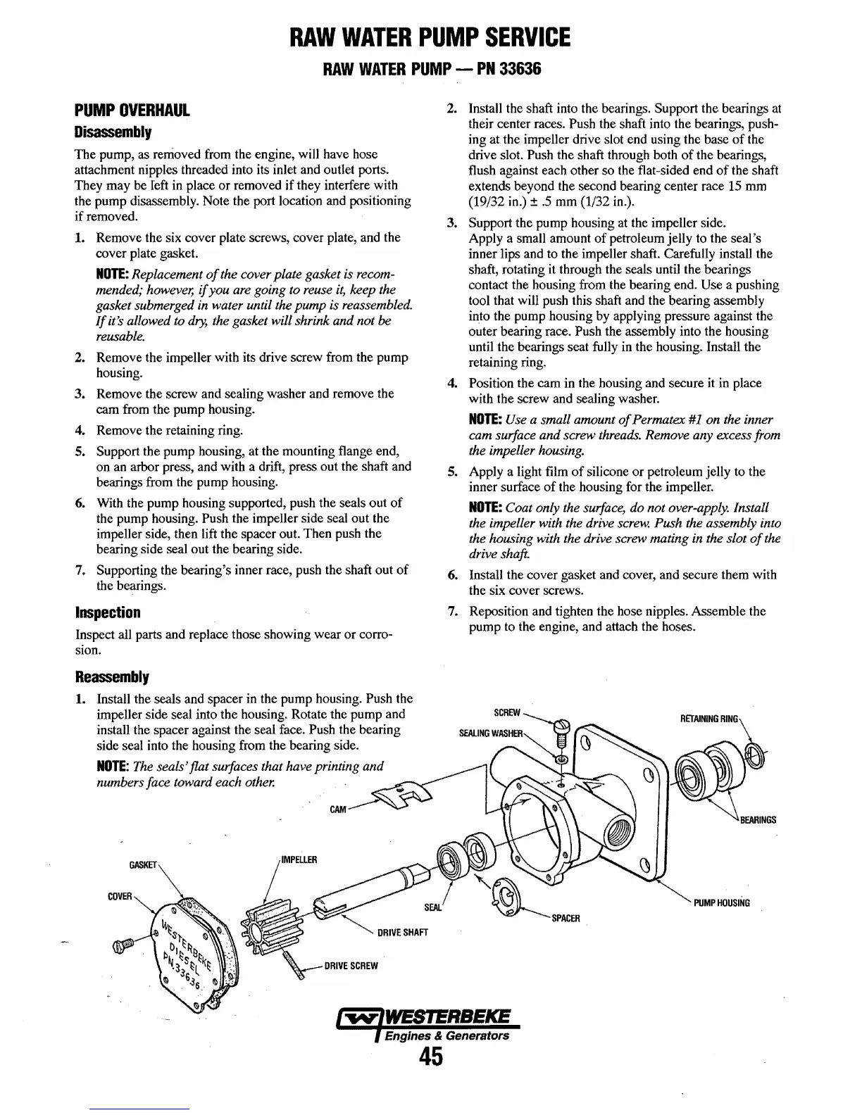
COVER
2. Install the shaft into the bearings. Support the bearings
at
their center races. Push the shaft into the bearings, push-
ing at the impeller drive slot end using the base
of
the
drive slot.
Push the shaft through both
of
the bearings,
flush against each other so the flat-sided end
of
the shaft
extends beyond the second bearing center race
15
mm
(19/32
in.)
±
.5
mm (1/32
in.).
3. Support the pump housing at the impeller side.
Apply a small amount
of
petroleum jelly to the seal's
inner lips and to the impeller shaft. Carefully install the
shaft, rotating
it
through the seals until the bearings
contact the housing from the bearing end.
Use a pushing
tool that will push this shaft and the bearing assembly
into the pump housing by applying pressure against the
outer bearing race.
Push the assembly into the housing
until the bearings seat fully in the housing. Install the
retaining ring.
4.
Position the cam in the housing and secure
it
in
place
with the screw and sealing washer.
NOTE:
Use a small amount
of
Permatex
#1
on the inner
cam surface and screw threads. Remove any excess from
the impeller housing.
5. Apply a light film
of
silicone
or
petroleum jelly to the
inner surface
of
the housing for the impeller.
NOTE:
Coat only the surface, do not over-apply. Install
the impeller with the drive screw.
Push the assembly into
the housing with the drive screw mating in the slot
of
the
drive shaft.
6. Install the cover gasket and cover, and secure them with
the six cover screws.
7. Reposition and tighten the hose nipples. Assemble the
pump to the engine, and attach the hoses.
PUMP
HOUSING
Engines & Generators
45
 Loading...


